The use of signal filtering for eddy current testing
Signal filtering can be considered necessary, almost mandatory, in the automated testing of long products like bars, wires, and tubes. Signal filtering is used to eliminate indications of frequencies irrelevant to the test. In other words, it can be seen as creating a window of frequencies very close to the “defect” signal frequency.
These irrelevant indications may originate from mechanical vibrations, electrical noise, instrumentation, sensors, variation in conductivity etc.
It may be noted that the term “defect” is used loosely here and denotes any artifact whose signal is of interest or relevant to the test. This note is valid for any non-destructive testing method like ultrasonic, radiography, thermography etc.
The importance of the right filter settings eddy current testing
Selecting the optimal filter settings can result in an increased Signal to Noise ratio, and adversely, selecting the incorrect filter settings can completely mask the “defect” or even eliminate it completely. This makes the selection of filters very critical and understanding it becomes very important.
At this stage, it should be clearly understood that the “defect” frequency is not the Test Frequency. The Test Frequency is the frequency of excitation of the eddy current sensor. The “defect” frequency depends on
- Effective width of the sensor
- The line speed for non-rotating eddy current testing
- The rotational speed for rotating eddy current testing
The easy way to remember this is that the “defect” frequency is a function of the speed at which the “defect” traverses past the windings of the eddy current sensor. This definition is valid for both rotating as well as non-rotating sensors.
“Defect” frequency is, therefore, also a function of the sensor width. The smaller the width, the higher the “defect” frequency.
How to set up the right signal filters
Once we have understood what the “defect” frequency is, it is easy to set up signal filtering. It may be seen as two limits, one each on the lower and upper side of this “defect” frequency.
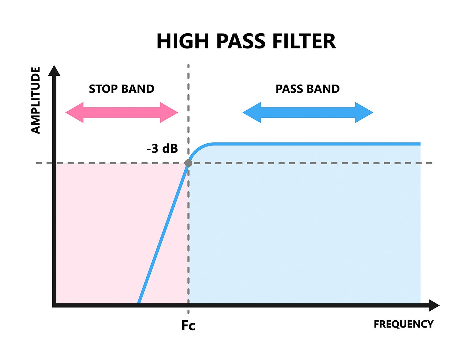
The lower limit is the High Pass (HP) filter setting (allows frequencies higher than that point).
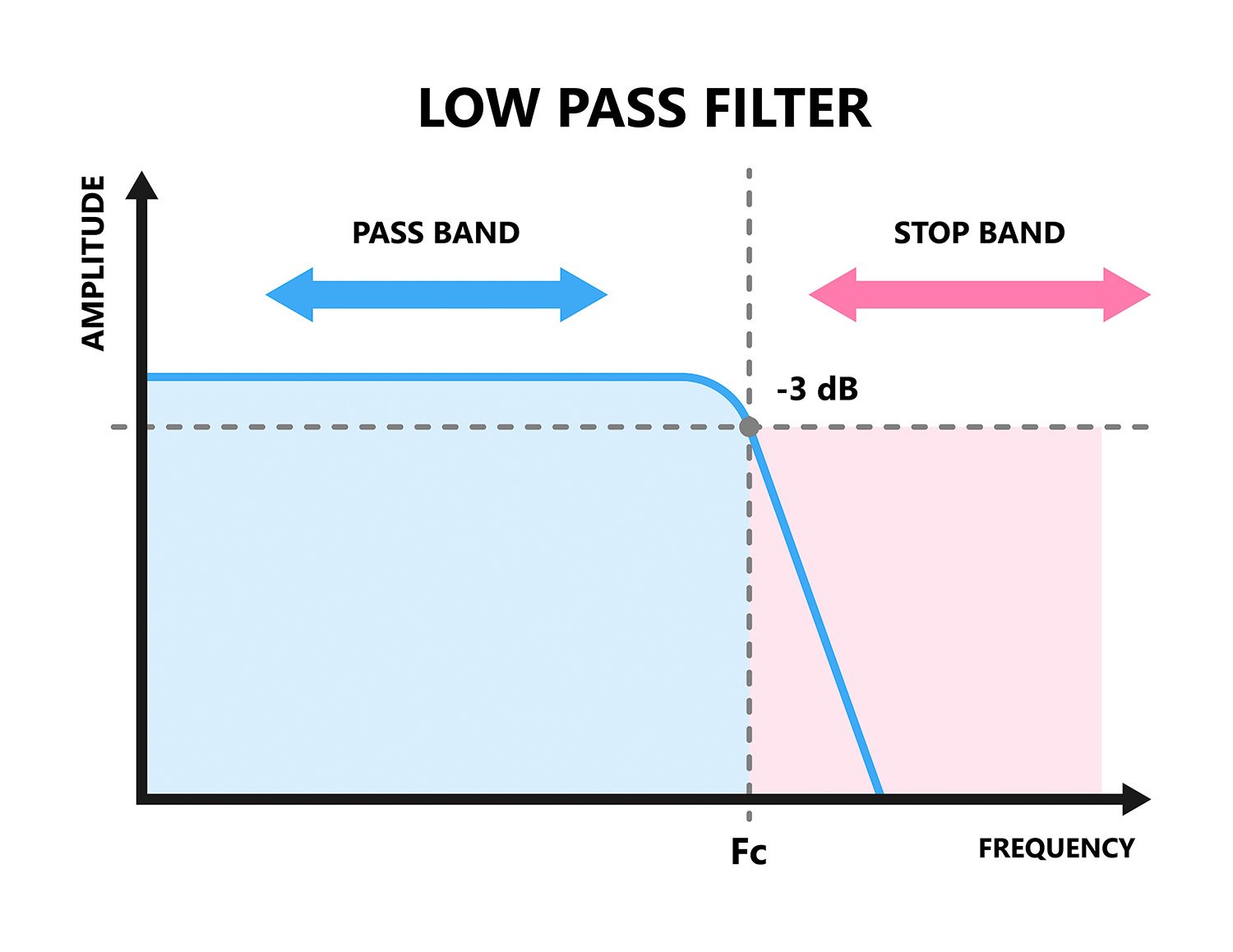
The upper limit is the Low Pass (LP) filter setting (allows frequencies lower than that point).
The HP and the LP settings together define a Band Pass Filter (BP).
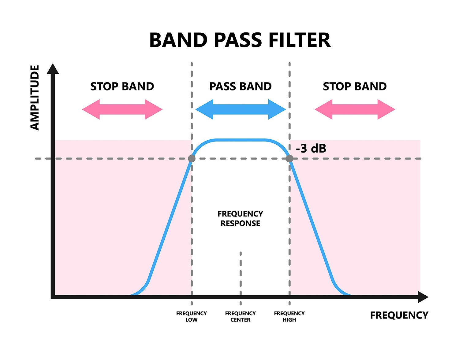
This BP Filer setting is what was mentioned in the first paragraph of this article as the “window of frequencies”
If the HP and LP settings overlap or cross over, the result would be a “Zero” BP or a negative BP filter setting. This condition would result in a masking or complete elimination of the “defect” frequency. Therefore, the HP setting should always be less than the LP setting.
Since all this is directly related to the “defect” frequency, the significance and importance of measuring the test speed accurately will be discussed in a subsequent article.
For more information and mathematics associated with Signal Filtering please call FOERSTER.

Share this
Harmonic analysis - 4 points to consider for eddy current testing
Automated testing of cylinder bores with the eddy current method