The economical solution for achieving low residual field strengths in the demagnetization of ferromagnetic materials
Demagnetization (or neutralization) of ferromagnetic material by a decaying magnetic alternating field is, by far, the most economical solution for achieving low residual field strengths. When doing this, the selection of the correct instrument parameters is just as crucial as the method of transportation and storage after demagnetization.
The influence of magnetic fields on demagnetized materials
This document is intended to provide tips on the treatment of demagnetized material and on possible 'sources' which may lead to re-magnetization.
The condition of the testing line plays a not inconsiderable role in this respect. Consequently, we shall also provide a few tips on this as well. We shall then say a few words on the subject of transportation and storage of demagnetized material. This involves complying with rules which will, initially, appear more than trivial but which are frequently not followed in practice. This document concludes with information on the correct method of determining the residual field strength and a checklist of measures indicating what to do if the residual field strengths achieved are not low enough.
This document does not discuss the procedure with which the appropriate setting of the demagnetization parameters (alternating field strength *, DC field strength, and frequency * in combination with wall thickness and line speed) are determined.
 Emag F
Requirements applicable to the line
The supporting structure of a coil should consist of the same material as the adjoining sections of the testing section. If the testing section is made of ferromagnetic steel, the same material should also be used for the area of the coil so that no major flux leakage which normally emerges at the ends of steel structures acts in the area of the coil. The supporting structure should consist of the same material without any gap throughout if possible. If this is not possible (owing to height adjustment), the air gap between the components should be small (1 mm) and the ferrous cross-section of the pole faces should be large.
The material should preferably be guided centrally through the coil. However, eccentric material guidance does not essentially impair demagnetization. The actual distance between the material and the coil tube may not be less than 5 mm.
The extraction forces from the demagnetized coils may be relatively high. A drive system with material clamping downstream is always practical and essential in thin or oiled bars, low material weights, or low transport speed.
Magnetic rollers for increasing the frictional forces between the drive and material may not be used!
Material drivers and support rollers downstream should have non-magnetic rollers e.g. rollers with non-magnetic bearing surfaces made of austenitic steel or PU (Vulcolan). If the minimum distances specified in the leaflet cannot be complied with, it is essential to use non-magnetic rollers. The smaller the material cross-section, the greater will be the problems when using magnetizable rollers.
Testing lines are always magnetized. The state of magnetization is not constant but is varied to a greater or lesser extent as the result of material stored nearby, as the result of testing of differing materials, and as the result of large-volume ferrous structures. Changes frequently take a few days to stabilize.
If a material with a small cross-section is demagnetized, external fields downstream of the demagnetized coils have a major effect. This is attributable to the fact that a relatively large magnetic flux is then guided through the material and the magnetization is frozen by the decaying field. Frequently, it is not possible to compensate for the flux in the material by the DC field setting owing to the small cross-section. When demagnetizing steel bars with a diameter of less than 15 mm and in the case of tubes with a wall thickness of less than 3 mm, it is thus practical to compensate for the external field with a block magnet. The block magnet must be arranged downstream, below the height of the coil support, in such a manner that the field in the material plane, approx. 150 mm downstream of the coil, is zero.
Welding work on testing lines influences the state of magnetization of testing lines. The welding current magnetizes the parts through which the current flows and the neighboring parts.
When carrying out arc welding, always attach the opposite pole directly at the welding location! The Annex provides further remarks applicable to a magnetized conveying mechanism.
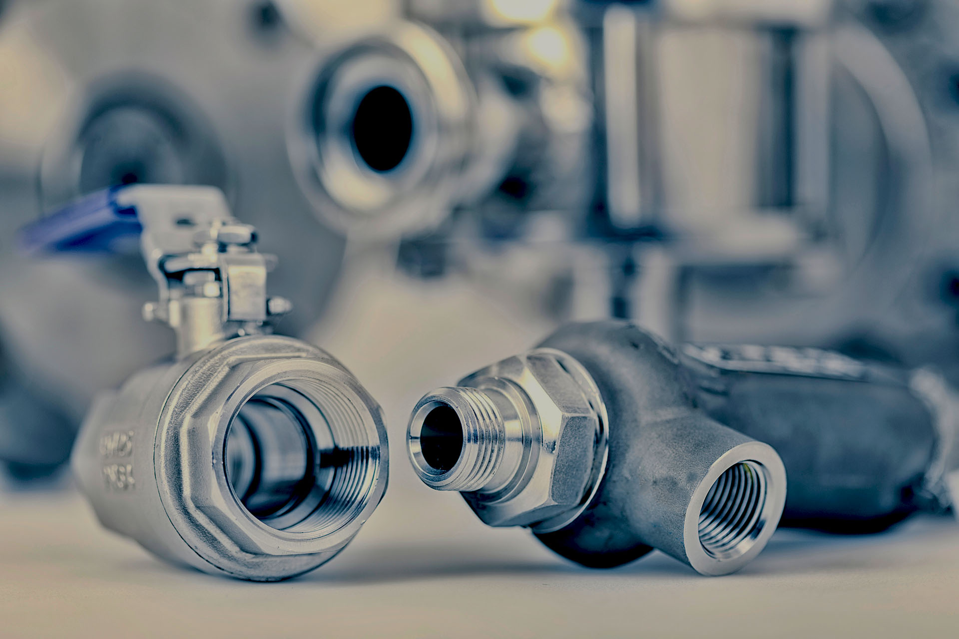
The product FOERSTER uses for the testing of the ferromagnetic material defects using the eddy current or flux leakage methods where the test materials are generally magnetized to saturation.


Share this
Why is demagnetization becoming an ever-increasing necessary process?
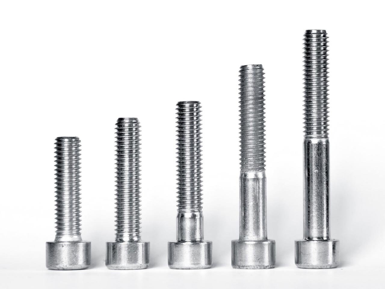
Hardness testing - so that fasteners & screws deliver what they promise