Eddy current coil types for hardness testing
Testing the surface hardness or the hardness curve with eddy current testing devices requires an optimized setup for the application. This consists of an optimal probe for the application and a specialized testing device.
The frequency range in which the application is to be carried out is a top priority. Prerequisites for this decision are application tests with samples that differentiate good from bad parts. For this purpose, application tests must be performed with both error-free and defective parts to validate the identified settings and determine limits concerning their relevance. This system validation is essential to prevent unnecessary rejects in the subsequent process variations and to avoid bad parts from being classified as good ones.

What is the setup for an eddy current based hardness test?
An eddy current-based hardness test or a hardness test with a magnetic-inductive test system requires:
- a coil,
- a cable that connects the coil to a test device,
- and the corresponding test device.
The test device usually contains software with the algorithms that evaluate signal curves and converts them into evaluable logic for the user.
Learn more about hardness testing with eddy current. Read our eBook about challenges and solutions for hardness testing. Click here!
What influence does the test frequency have on the selected coil?
The coils designed for the application consist mostly of copper wires wound on a ferritic core or air coils. These represent the primary and secondary inductance. The functionality of the magnetic inductive hardness test is based on the interaction between a generated magnetic inductive alternating field and the test object. The alternating magnetic field is generated by a sinusoidal current in a primary coil. It generates an opposing field in the specimen as a result of the eddy currents. This opposing field takes effect on a secondary coil in the probe and generates an induction voltage. This interaction of the primary and secondary coils can be recorded and evaluated in the device hardware. The copper winding generates the inductors. These are designed for the frequency ranges of the test. At very high frequencies, the inductances of the coil winding are usually very small. For very low frequencies large inductances are usually required. Furthermore, the selected coil current has a decisive influence on the design of the coils. The coil current is in turn proportional to the magnetic flux generated in the test part.
Which coils and probes are used for hardness testing?
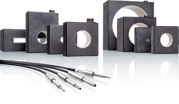
Two basic forms of coil design can be distinguished:
- ring-shaped or square-shaped coils
- and pen probes.
For the construction of ring-shaped or corner-shaped coils, the primary and secondary coils are wound on one level and encapsulated in a hermetic housing. In the middle of the coil housing, there is an opening in which the test specimen is tested. These types of spools can be easily integrated into conveyor belts and automated lines. Each test object triggers a measurement when it passes through the coil in the test system. The system logic analyses the result and decides if the test part may continue to run on the system or should be sorted out as faulty. This setup offers advantages in the handling and reproducibility of the measurement results. However, the accuracy of the measurement depends on the positioning of the test part as it passes through the test coil as well as of a constant test speed. If these factors are limited, more varied measured values follow. This can make it necessary to expand the defined test limits.
The second form of design is a pen probe. For the construction, a primary and secondary winding are housed in the test probe. To concentrate the field on the tip of the probe, both windings are placed in a coil housing, usually a kind of ferritic rod or pot-core. The general difference between a pen and a coil probe is that in the former the component has to be stopped briefly during the test process. To do this, the conveyor system stops the test part, a feed mechanism moves the test probe to the test object and triggers the test. With the transmission of the information related to the good and bad pieces, the test system triggers the automated unit and the next component is moved to the test station. Even if the cycle times that can be achieved with pin probes are generally lower than with ring-shaped or corner-shaped coils, the repeatability of the measurement is superior.
A high test quality in production requires the right test strategy. In addition to the design of the test coils which is qualified for the respective application, the choice of parameters, frequencies, suitable harmonics, and the correct test system is also decisive.
With the MAGNATEST D, FOERSTER provides a proven test system that can handle a wide range of test tasks.

Share this

Crack testing: How does an eddy current test instrument work?
Crack testing: How do I set my filters and frequencies correctly?