Crack testing with eddy current offers a practical way to detect surface defects such as cracks or pores. Correctly adjusted filter settings in terms of defect size, probe track width and rotation speed are essential for successful eddy current testing.
A brief introduction to crack testing
The crack testing can be performed statically or dynamically. In dynamic crack testing, either the sensor, in which the exciter and measuring coil are installed or the part to be tested is set in constant rotation. A test probe with a specific track width tests the defined test area. If the test area is larger than the track width, the probe moves over the surface and scans it. If the surface of the test part has no inclusions or damage, the eddy currents flow evenly in the material. As soon as inclusion or crack appears in the surface of the test piece, the electrical resistance changes and the eddy current becomes smaller or has to "swerve". This changes the eddy current density. This change is detected and evaluated by the measuring coil. This type of non-destructive, dynamic crack testing can be used automatically and is used, for example, on many components in the automotive industry.
Click here to get more information about Automated Crack Testing!
In static crack testing, the sensor is moved by hand over the surface of the test part; this type of testing takes place, for example, during maintenance inspections of various safety-relevant components in the aeronautic industry.

In summary, crack testing with eddy current offers a viable way to detect surface-open defects such as cracks or pores.
The correctly adjusted settings of the filters in terms of defect size, the track width of the probe, and rotation speed are essential for successful eddy current testing. An optimized setting of the test parameters improves its stability and significantly reduces pseudo-rejects.
Filtering possibilities of the error signal using the eddy current test method
1. Test frequency
The correct selection of the specific magnitude of the test frequency depends on the requirements of the application, the specific probe, and the electrically conductive material to be tested. The test frequency determines the so-called penetration depth, i.e. the distribution of eddy currents in the depth of the material surface.
In addition, eddy currents are strongly dependent on the distance of the probe to the respective material or test surface.
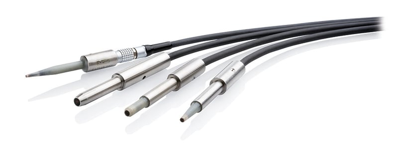
Probes for the non-destructive crack detection using eddy current
The higher the test frequency, the greater the number of eddy currents generated at the material surface. On the other hand, the eddy current strength or its penetration depth at the surface decreases rapidly with increasing test frequency. In other words, relatively high test frequencies are used to detect open-surface defects. In this context, it should be mentioned that the electrical conductivity and permeability (permeability of material for magnetic fields) have the same influence on the distribution of the eddy current strength as the selected test frequency. Therefore, with the selection of the test frequency, both the test sensitivity and the material penetrated by eddy currents can be specifically adjusted.
The high test frequencies create eddy currents on the surface of the test part and deliver optimum sensitivity to exposed cracks or pores.
Low test frequencies, on the other hand, provide better sensitivity for defects located close below the surface due to the greater penetration depth.
2. High-pass filter
High-pass filters suppress low-frequency disturbances, such as slow changes of position or fill factor. The test frequency to be set here depends largely on the relative speed between the test probe and the test part. If the filter is set too narrow in comparison to the feed rate, error signals will be suppressed and the inspection cannot be carried out reliably.
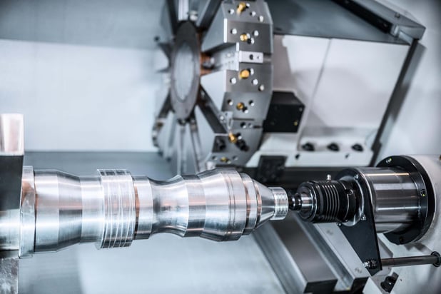
High-pass filters are mostly used for rotating tests. Here, the surface speed depends on the speed of the constantly rotating unit (e.g. lathe). High-pass filters can be used, for example, to filter out conductivity differences, geometry variations, but also distance signals ("lift-off").
It should be noted that the frequency spectrum of the interfering signals and the specified error signals depends on both the respective test speed and the characteristics of the sensor used:
- The greater the test speed and the smaller the probe track width,
the higher the frequency of the signals will be. - The smaller the test speed and the larger the probe track width,
the lower the frequency of the signals will be.
3. Low-pass filter
Low-pass filters are used to suppress interfering high-frequency signals of the frequency band, while the frequencies below a certain cut-off frequency (specific error signals) remain unaffected.
In eddy current crack detection, low-pass filters are used to suppress, for example, high-frequency electromagnetic fields or electronic noise from the test equipment. It should be noted that the frequency spectrum of the interference signals and the specific error signals depends on both the test speed and the properties of the sensor used.
The cut-off frequency of the low-pass filter is set accordingly when the higher-frequency interference signals are effectively suppressed, with the specific error signals still being displayed with maximum signal amplitude.
An optimal setting of high-pass and low-pass filters without suppression of the error signals can improve the so-called signal-to-noise ratio (SNR) between the error to be resolved and the background noise of the test material. The higher the SNR of a test, the more stable the test will be. A high SNR means that fewer pseudo rejections are expected.
FOERSTER offers devices for crack testing of complex workpieces with eddy current
To make crack testing even simpler and more intuitive, FOERSTER has extensively developed the STATOGRAPH. To guide and assist operators in determining the optimal filter setting, FOERSTER's STATOGRAPH CM 6.470 features automatic parameter optimization.

STATOGRAPH CM
FOERSTER has further improved its high- and low-pass filters to ensure that every surface defect is reliably detected. The filters can be fine-tuned to screen out interference signals. And with its optimized distance compensation function, the system can compensate for even greater differences in distance.
Feel free to contact our experts and discuss your testing tasks. We are glad to help you!

Share this

Crack testing: How does an eddy current test instrument work?

Eddy Current Instruments: advantages, applications, and capabilities for defects detection