Crack detection remains one of the most important applications in non-destructive testing (NDT). The right inspection strategy helps you identify defects early, reduce scrap, maintain compliance, and protect both product performance and customer trust.
However, not every crack testing method works the same way. Different materials, component geometries, production environments, and defect types require different inspection approaches. Choosing the wrong method can lead to inconsistent results, unnecessary scrap, missed defects, or inefficient production workflows.
Feeling overwhelmed and not sure where to begin? You are not alone. Below, we break down six of the most important crack testing methods used in modern manufacturing and explain where each method delivers the greatest value.

Why is Non-Destructive Material Testing Necessary?
Cracks often begin as microscopic discontinuities that are nearly impossible to detect visually. Over time, these defects can grow under stress, vibration, heat, pressure, or fatigue until they compromise the integrity of an entire component.
In many industries, a missed defect does not just affect a single part. It can impact:
-
Production uptime
-
Operator safety
-
Regulatory compliance
-
Customer confidence
-
Long-term equipment reliability
If you are operating in high-throughput production lines, the challenge becomes even greater. Inspection systems must detect increasingly small defects while maintaining speed and repeatability across thousands of parts.
In safety-critical applications, even minor defects can have serious consequences. If an automotive component fails during operation in a vehicle, human lives are immediately endangered. If a pipeline or structural component develops an undetected crack, the resulting damage can lead to costly downtime, repairs, and operational disruptions.
Because of these risks, industries such as automotive, aerospace, energy, and heavy manufacturing maintain strict quality and inspection standards. These requirements ensure that safety-relevant components are continuously inspected throughout production and before installation.
What Types of Defects Can Be Found During NDT Surface Inspection?
The range of possible material defects varies depending on the component application, material type, geometry, and manufacturing process. Some of the most common defects identified during non-destructive surface inspection include:
-
Cracks
-
Cavities
-
Dents
-
Grinding burn
-
Hard spots
-
Soft spots
-
Magnetic inclusions (remanence)
Among these, surface cracks remain one of the most critical defects to detect reliably. A common example is cracking in brake discs. Small surface cracks may initially appear harmless, but repeated loading and temperature fluctuations can cause them to propagate. Over time, this can compromise braking performance and create potentially dangerous operating conditions.
Because of this, your inspection systems should be capable of detecting defects as small as a few thousandths. Eddy current testing is widely used for these applications due to its sensitivity, speed, and suitability for automated inspection environments.
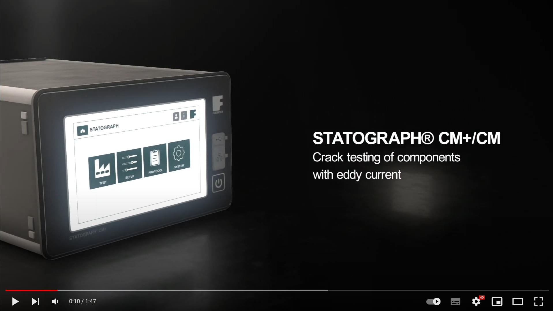
Systems like the STATOGRAPH are designed to detect extremely small surface defects with high repeatability. Depending on the component material, probe configuration, and testing frequency, cracks as small as 25 µm can be reliably identified.
Ultimately, selecting the appropriate crack testing method is not simply about finding defects. It is about implementing an inspection strategy that aligns with the material, application requirements, production environment, and overall risk profile.
Which Methods Are Available for the Detection of Cracks in Cast Components?
Before discussing specific crack testing methods, it is important to understand the difference between destructive and non-destructive testing.
Destructive testing literally involves cutting, breaking, or permanently altering a component to evaluate its material properties or overall performance. While these methods are valuable for validation and laboratory analysis, they cannot be applied to every manufactured part.
Non-destructive testing (NDT), on the other hand, allows you to inspect components for defects without damaging the material or affecting usability. This makes NDT especially valuable in modern production environments where fast, repeatable, and highly reliable inspection results are required across large volumes of components.
Unlike destructive testing, which is typically limited to sample analysis, NDT methods can be integrated directly into production lines to support continuous quality monitoring of every part. Many modern NDT systems also reduce operator dependency through automated, data-driven inspection processes that improve consistency and traceability.
As manufacturing tolerances become tighter and quality expectations continue increasing, inspection repeatability and reliability are becoming just as important as defect sensitivity itself.
Today, you can use several common crack testing methods depending on the application, material, geometry, and inspection requirements:
Each method offers different advantages depending on material type, component geometry, expected defect characteristics, inspection speed, automation requirements, and overall production goals.
The objective is not simply to find defects, but to implement an inspection strategy that balances sensitivity, repeatability, throughput, and operational efficiency.
Comparison of Common Crack Testing Methods
When looking for an inspection system, you should prioritize one that provides reliable, scalable, and repeatable results. The comparison below highlights how different crack testing methods align with today’s production and quality assurance requirements.
|
Method |
Best For |
Key Advantages |
Main Limitations |
Repeatability |
Automation Potential |
|
Visual Inspection (VT) |
Basic surface condition checks and visible defects |
Fast, simple, low cost |
Highly dependent on operator experience and lighting conditions |
Low |
Moderate |
|
Dye Penetrant Testing (PT) |
Fine surface cracks and pores on finished components |
Sensitive to small surface defects, widely used |
Multi-step process, manual interpretation, surface preparation & chemicals required |
Moderate |
Low |
|
Eddy Current Testing (ET) |
Conductive materials and high-speed surface crack detection |
Extremely fast, highly sensitive, ideal for inline inspection and automated sorting |
Limited penetration depth, requires conductive materials |
High |
High |
|
Thermographic Testing (TT) |
Complex geometries and non-contact crack detection |
Flexible for varied part shapes, supports automated imaging and analysis |
Surface contamination can affect results, advanced analysis required |
High |
High |
|
Magnetic Particle Testing (MT) |
Surface cracks in ferromagnetic materials |
Strong defect visibility, effective for maintenance and field inspections |
Cleanup required, subjective evaluation, limited automation, time-consuming |
Moderate |
Low |
|
Ultrasonic Testing (UT) |
Internal and subsurface defects |
Deep penetration, accurate internal defect detection |
Requires coupling medium and skilled setup |
High |
Moderate to High |
1. Crack testing with visual inspection (VT)
Visual inspection (VT) is often the first step in both destructive and non-destructive testing processes. Operators evaluate visible surface conditions such as cracks, dents, and shape deviations using the naked eye or optical tools like microscopes or endoscopes.
Because it can be applied across many component types and materials, visual inspection remains widely used for production monitoring and maintenance inspections. However, the process relies heavily on operator experience and subjective interpretation, which can make consistent defect classification more difficult compared to automated NDT methods.

2. Crack testing with dye penetrant testing (PT)
Dye penetrant testing (PT) uses capillary action to identify fine surface cracks and pores that may not be visible during standard visual inspection. A liquid penetrant seeps into surface discontinuities and highlights defects after excess material is removed.
The method is commonly used on metals and other non-porous materials because it offers high sensitivity for small surface defects. However, the inspection process remains highly manual and depends on consistent surface preparation and operator evaluation.

3. Crack testing with eddy current instruments (ET)
Eddy current testing (ET) has become one of the most widely used methods for detecting surface cracks in conductive materials. The technology uses electromagnetic fields to identify changes in signal behavior caused by cracks, pores, or other discontinuities.
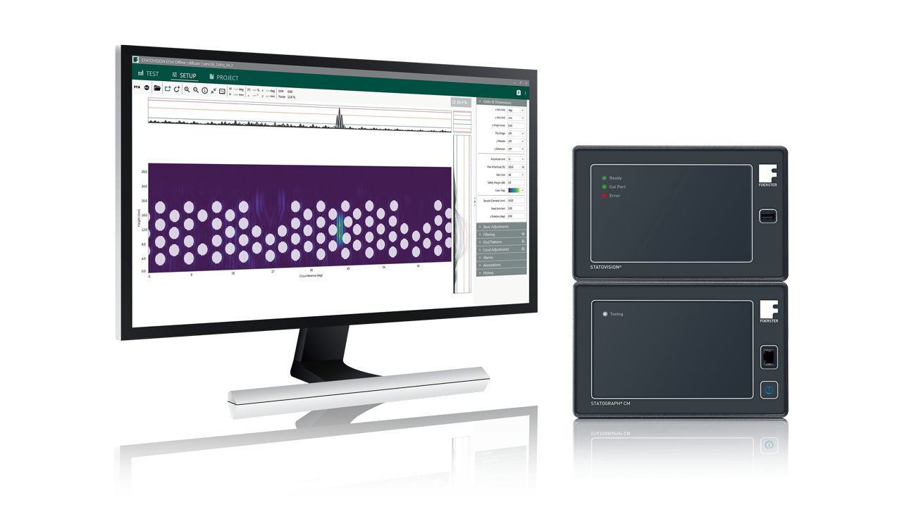
Because eddy current systems collect and process data at extremely high speeds, the method is especially effective for automated inline inspection environments. Solutions such as STATOGRAPH and STATOVISION help manufacturers improve repeatability, optimize signal evaluation, and reliably detect defects as small as 30 μm depending on the application setup.
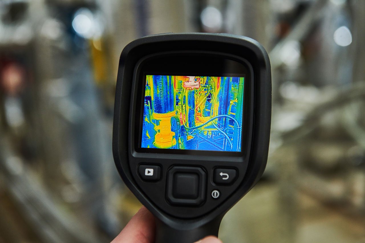
4. Crack testing with thermographic equipment (TT)
Thermographic testing (TT) is becoming an increasingly important crack detection method for components with complex geometries or applications where traditional eddy current testing may be limited. During the process, a component is briefly heated while a thermographic camera captures how heat flows across the surface.
Cracks and other discontinuities react differently to heat and appear clearly in the thermal image. Because the method supports both conductive and non-conductive materials with fewer geometry limitations, thermographic testing is gaining traction in automated production and quality assurance environments.
5. Crack testing with magnetic particle testing equipment (MT)
Magnetic particle testing (MT) is one of the oldest and most widely used methods for detecting surface cracks in ferromagnetic materials. Components are magnetized and coated with magnetic particles that gather around defects where the magnetic field is disrupted, making cracks visible to the inspector.
While the method remains effective for identifying surface flaws, the process depends heavily on operator interpretation and requires significant post-inspection cleaning. As a result, magnetic particle testing is often better suited for maintenance applications, field inspections, and lower-volume testing environments.
6. Crack testing with ultrasonic instruments (UT)
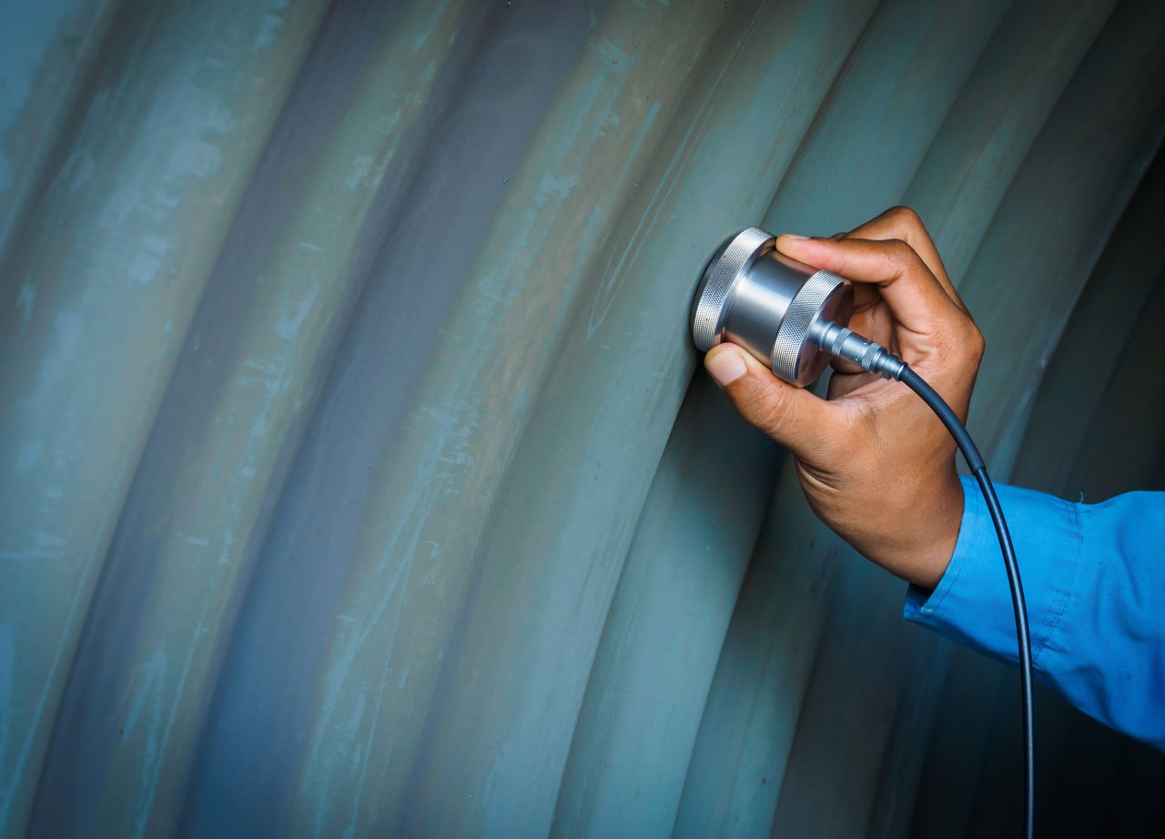
Ultrasonic testing (UT) is commonly used when manufacturers need to detect internal cracks or subsurface material anomalies that surface-focused methods cannot reliably identify. The process uses high-frequency sound waves transmitted into a component through a coupling medium to evaluate the internal structure of the material.
As the sound waves travel through the test part, reflections caused by cracks or inclusions are captured and analyzed to determine the location and size of potential defects. Because ultrasonic testing can inspect deep within a component and works across a wide range of materials, it remains one of the most effective methods for identifying internal flaws in safety-critical applications.
Moving From Defect Detection to Process Reliability
Detecting cracks is only part of the challenge. In modern manufacturing environments, inspection systems must also deliver consistent, repeatable results at production speed.
As tighter tolerances and throughput demands increase, you may face growing pressure to reduce false rejects, minimize operator dependency, and maintain reliable quality standards across every shift and production run.
This is where automated non-destructive testing systems provide significant advantages. Modern eddy current technologies, digital signal processing, and integrated software platforms help you move beyond subjective pass/fail evaluations by delivering data-driven inspection results with greater consistency and traceability.
For example, FOERSTER’s STATOGRAPH testing systems are designed for highly sensitive detection of surface cracks in conductive materials. When this system is combined with advanced evaluation software such as STATOVISION, you can further optimize signal quality and adapt inspection parameters for multiple defect patterns and production requirements.
In high-volume production environments, these capabilities support:
-
Improved inspection repeatability
-
Automated defect classification
-
Reduced scrap and false rejects
-
Faster inspection speeds
-
Greater confidence in the final product quality
From standalone testing instruments to fully integrated inline inspection systems, FOERSTER provides scalable crack detection strategies that align with modern quality assurance and production goals.

Captions
- A = Works extremely well
- B = Works well
- C = Not the best choice
- D = Does not work
Next Steps for Improving Crack Detection Processes
Improving crack detection starts with understanding where defects are most likely to occur and whether your current inspection process detects them. Surface cracks, flaws, production speed, component geometry, and material type all influence which testing method will deliver the best results.
If you haven’t already, now’s a good time to evaluate if your current inspection process provides consistent, repeatable results across operators, shifts, and production runs. In many cases, repeatability and reliability become just as important as defect sensitivity, especially in high-volume production environments.
As throughput demands increase, it is important to consider whether existing inspection systems can support automation, inline integration, digital traceability, and faster decision-making without sacrificing accuracy. Modern NDT technologies are increasingly designed to reduce operator dependency while improving overall process consistency.
The most effective crack testing strategies also take a long-term view of quality assurance. Rather than simply identifying defects, be on the lookout for solutions that help reduce scrap and rework, improve confidence in final product quality, and support evolving production requirements over time.
Finally, inspection technologies continue advancing through automated evaluation software, digital signal processing, thermographic imaging, and integrated inline systems. Staying informed about these developments can help you build more scalable and future-ready quality assurance processes.
When reviewing your current crack testing strategy, consider asking:
-
Are we detecting the right types of defects for our application?
-
Does our inspection process deliver repeatable results across shifts and operators?
-
Can our current testing method keep pace with production demands?
-
Are we relying too heavily on manual interpretation or subjective evaluation?
-
Could automation or digital evaluation improve consistency and reduce false rejects?
-
Are our inspection systems flexible enough to support future production requirements?
These questions can help identify opportunities to improve inspection reliability, production efficiency, and long-term quality performance.
Share this
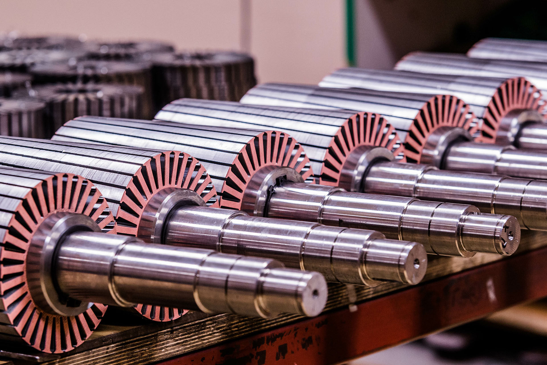
Microstructure and crack testing on rotor shafts using eddy current
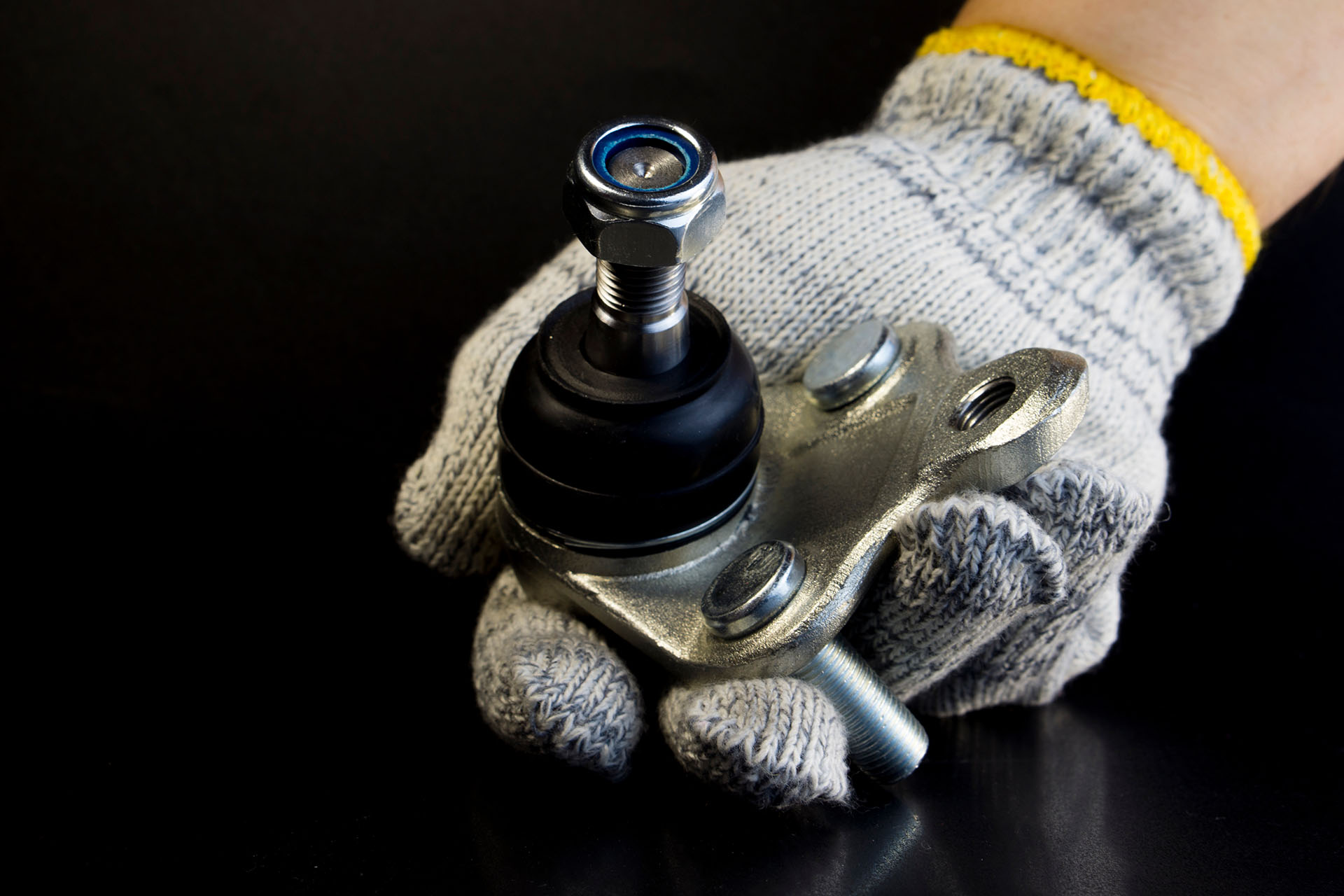
Automated crack testing of ball pins
