This blog post describes how application tests are performed on components using non-destructive testing methods. The focus is on detecting quality problems such as cracks and hardness defects. The article provides insight into the methodology of the eddy current testing process and highlights the importance of sensor selection, test frequencies and microstructural testing. Finally, application reports are discussed.
In the manufacturing process of metal components, quality problems such as cracks or hardness defects can occur. Detecting these in time and sorting out the defective components is important to ensure that the end product is free of defects.
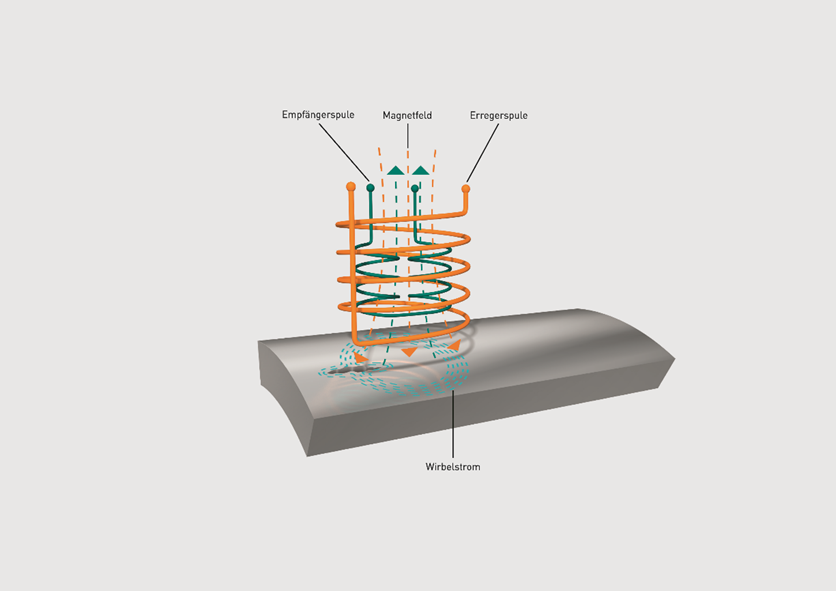
These material defects can be detected with the non-destructive eddy current testing method. Using high or low frequency electromagnetic interactions, defects such as cracks, pores or structural differences can be detected and evaluated manually or automatically, depending on the requirements. To find the defects, the eddy current testing method is based on a comparison with reference defects. Therefore, in a feasibility study during application tests in our application laboratory, the optimum result is determined based on samples provided by the customer, both for the technical equipment and the correct setting parameters. For this purpose, FOERSTER has a special team of application engineers who are in close contact with the developers and have a great deal of application knowledge. The results are made available to you in a detailed report and discussed personally on request.
The correct test frequencies, setting parameters, fault thresholds and sensor configurations are determined in the application tests. Among other things, the material properties, surface finish and defect characteristics play an important role.
In today's production, appropriate quality control is essential. The eddy current testing method can provide you with valuable information about the quality of your components. By detecting cracks or hardness defects at an early stage, you as a manufacturer can intervene in the production process in time, carry out optimizations and change machining processes to deliver high-quality products in the end.
Use cases that can be investigated in the application lab.
When testing components, two important tests often come into play. The inspection for surface defects and the microstructure inspection. For reliable testing, it is necessary to select the optimum setting parameters and the right sensors. Using various examples, we would like to outline the necessary procedure in the application laboratory:
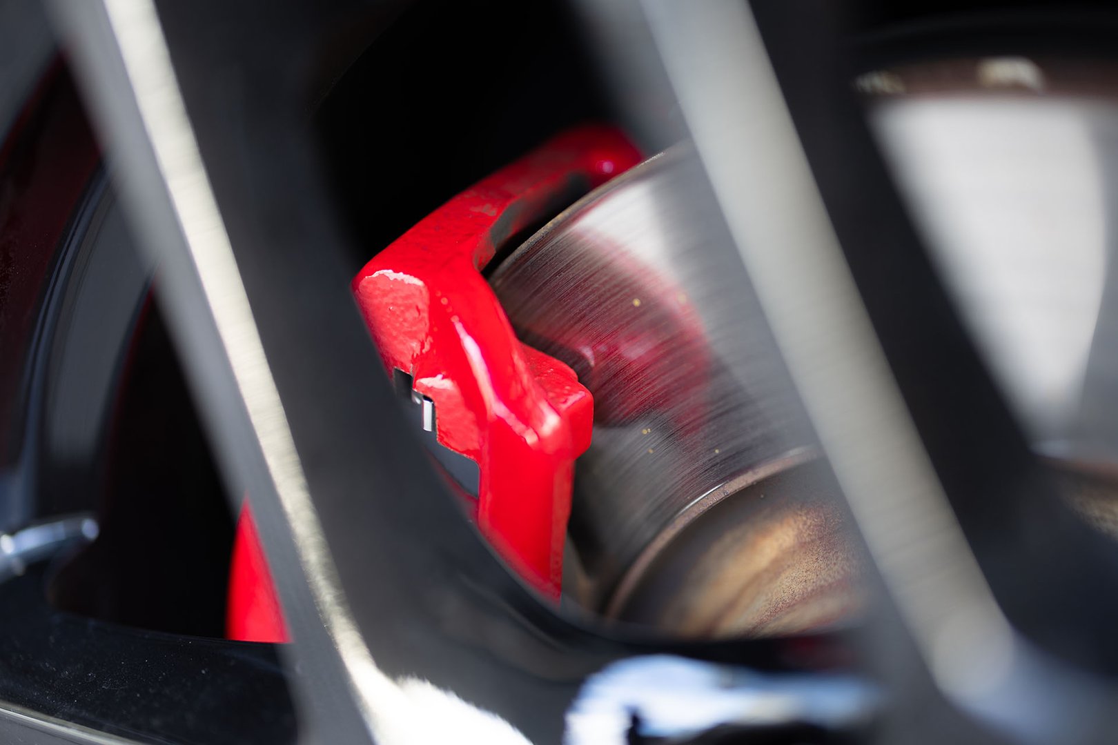
Scenario 1: Inspection for surface defects such as cracks
Rotation speed: The eddy current method is suitable for rotationally symmetrical components, as rotation is used here to detect defects such as cracks. Therefore, in application tests at our application laboratory, the components to be examined are clamped in a lathe. In this way, the optimum surface speed is determined, which facilitates the detection of surface defects. By carefully analyzing the magnetic field reactions during rotation, the exact location and severity of the cracks can be accurately determined. Transferred to use in production, this allows corrective action to be taken quickly in the event of quality defects.
Sensor selection: Another major influence on the inspection is the appropriate sensor. Depending on the component and application, FOERSTER offers a diverse selection of the most varied sensors. Therefore, various, specific sensors are used in the feasibility studies, which are selected based on factors such as material conductivity, surface properties, and the size and position of the areas to be inspected. Depending on the application, angled sensors, borehole probes or even flexible probes are then also used, for example - always with the aim of reliably detecting the required surface defects.
Test parameters and optimization: Once the correct rotation speed has been selected and the appropriate sensor has been found, the test parameters must be correctly set and optimized on the device. This includes selecting the correct excitation current, determining the test frequencies and, if necessary, setting the appropriate high-pass and low-pass filters. Furthermore, fault thresholds are defined, and other parameters are adapted to the application, i.e., to specific material properties and the fault characteristics.
Derived from this feasibility study, the optimum set-up for the inline or offline testing process is then compiled for you and discussed with you. You can read more about this below in "Application report & customer communication".
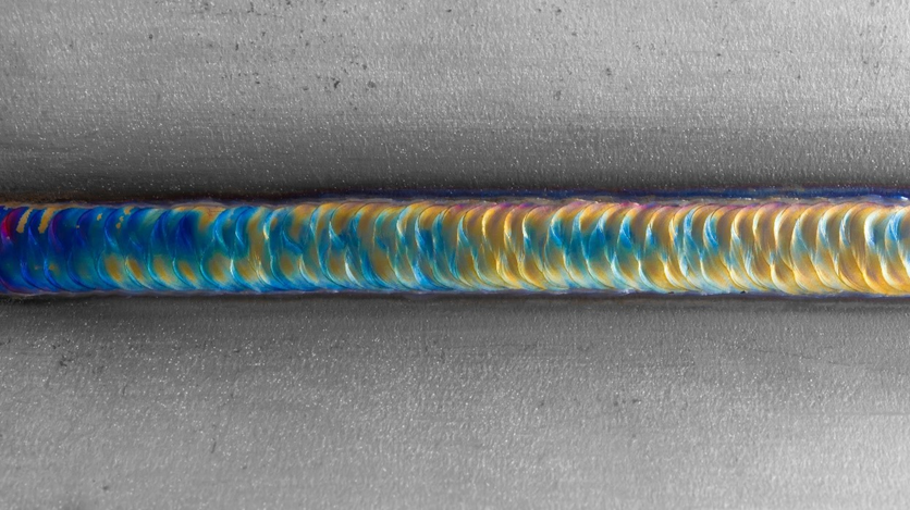
Scenario 2: Microstructure testing to determine material properties
Material mix-up: Despite extreme caution, material mix-ups can occur in the production process. These can cause considerable economic damage to tools in the production line and even consequential damage to users. To avoid this, magnetic induction microstructure testing can be used. Since the hysteresis curve is strongly influenced by technological parameters such as hardness, alloy constituents and microstructure, the magnetic properties of the material can be used to determine these parameters particularly well, thus components whose parameters are not correct can be sorted out. In the application laboratory, the magnetic characteristic values are determined based on reference parts and sorting limits are formed so that the components can be tested in the automated production process and then automatically sorted.
Sensor selection: A wide variety of sensors are also available for automated microstructure and hardness testing to enable optimum testing. For example, there are also special sensors for checking the edge hardness of machined components. The sensors are always selected based on the part geometry and position to provide precise results.
High-performance harmonic evaluation: We know: Laboratory conditions do not prevail in the production process. Performant harmonic evaluation is used to compensate for temperature and batch influences, eccentric component feeding and component tolerances, for example. Here, the magnetization curve is decomposed into fundamental wave and harmonics (multiples of the fundamental wave) by a Fourier transformation. The frequency spectrum includes all odd frequencies, i.e., f1 (fundamental), f3, f5, f7, etc. By evaluating the harmonics, additional information about the properties of the test material can be obtained. This minimizes the influence of external factors on the test results.
Application report and customer communication
Upon completion of the application trials and feasibility studies, the application engineer prepares a comprehensive report documenting the test procedures, results, and recommendations. This report provides detailed insights into the quality of the machined parts, as well as recommendations on how automated quality control could work in the process. Based on this report, an appropriate inspection solution for your process can then be developed in collaboration with our sales and engineering departments. The possibilities range from automated test cells or lines directly in your production process to offline test lines or solutions for random sample testing. Together with you, we will determine the optimal solution for you to check and objectively assess the quality of your components. Because of course, all test results are recorded in automatic test protocols so that you can prove the quality accordingly.
Application trials: the beginning of our cooperation
Do you have quality problems in your production and want to get to the bottom of this issue? The first step is our extensive application tests and feasibility studies, in which we make your problems visible and develop a solution with you to assess the quality of your components automatically and objectively.
The extensive tests are necessary to put together a test system for you that is optimally tailored to your application. Because only a perfect interaction of test parameters, the right equipment considering the material as well as defect properties and the process conditions, a reliable and sensitive test system can be built. Our application tests already provide valuable knowledge about your production process. This enables us to detect faulty production processes and to initiate process improvements.
Comprehensive application reports and effective communication are crucial for sharing results, recommendations, and solutions. Therefore, we strive to find an optimal testing solution for each specific application in an open discussion with our customers.
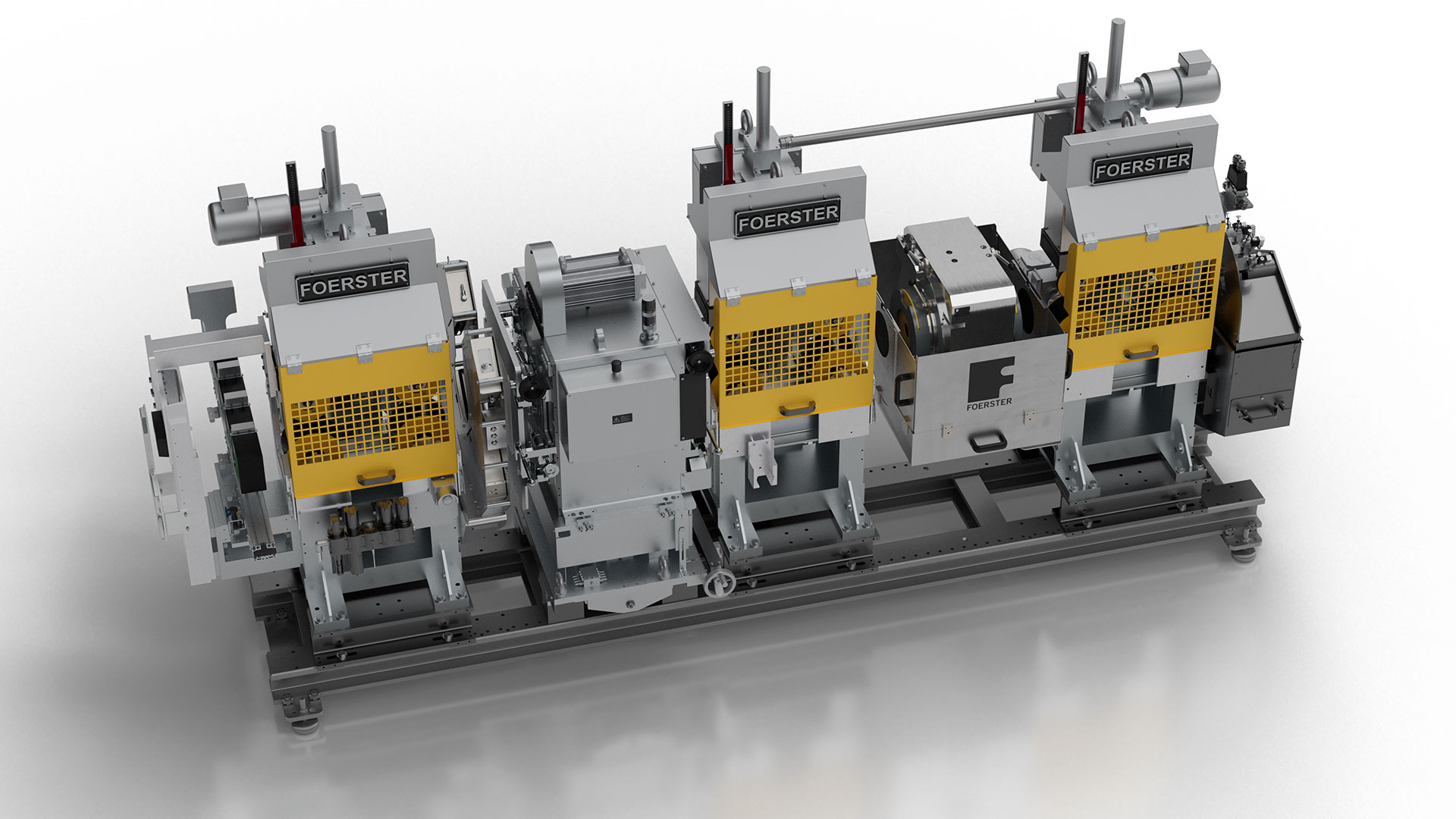
Our testing equipment has already proved itself for decades and makes quality visible in many industries. These include the STATOGRAPH CM/CM+ 6.470 testing systems for the detection of cracks, pores, and other surface defects as well as the MAGNATEST TCL and MAGNATEST D for hardness and microstructure testing.
If you would also like to know more, please book an appointment with our application laboratory today to help elevate the quality of your products.


Share this
Comprehensive guide for a one stop Non-Destructive Testing solution

Automated hardness and structure testing of metallic components