Eddy Current Instruments: advantages, applications, and capabilities for defects detection
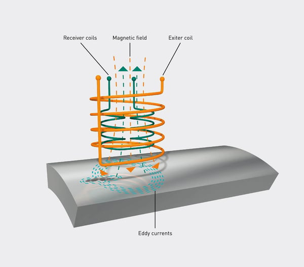
Eddy current testing: The eddy current testing is a non destructive test method for conductive materials to detect surface defects like cracks, pores or inclusions. For this, a probe is moved contactless over the test part. Inside a probe are two coils. One of the coil is used as transmitter coil, which is supplied with an alternating current.
These alternating current generates an alternating magnetic field (primary field), which induces eddy currents in the test part. These eddy currents generates also a magnetic field (secondary field), which according to the law of Lenz counteract against the temporal change of the primary field. A receiver coil measures the induced voltage of the resulting magnetic field.
Fig.1: Eddy Current Testing principle
The high frequency electromagnetic interactions are used for the crack detection (Fig. 2). Suitable electronics can analyze the receiving signals while scanning the test parts to get information about the surface conditions. If there are no inhomogenities on the surface, the eddy currents can flow homogeneously in the material. When the electric flow is disturbed by resistance (cracks, pores), the eddy currents have to flow a different way, which leads to a change of the amplitude and phase of the receiver signal.
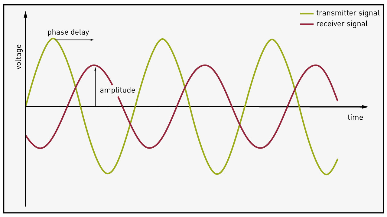
Fig.2: Electromagnetic interactions
Depending on the requirements, these changes can be recognized and evaluated manually or automatically.
Under optimal conditions, defect resolutions of up to 30 µm are possible. Since the test is contactless, surfaces are neither damaged nor soiled by the eddy current inspection.
Modern sensor, electronic and software solutions offer a wide range of application and evaluation options, including mobile use for maintenance testing.
Media consumption and maintenance costs are so low that eddy current testing is one of the most economical and environmentally friendly methods of non-destructive testing and is therefore also widely used for 100% testing in production processes. In addition, thanks to the high testing speeds and the ability to automate the test, the production process is not disturbed.
In the automated test variant, bad parts, so-called n.o.k. parts, are automatically detected due to the different signal compared to the good parts. The test electronics then send an impulse to the PLC, which sorts out the bad parts. This allows the number of rejected parts to be tracked and statistics on the defect rate to be kept. With a C-scan, in which the part surface is visualized as a 2D image, the exact position of the defect can be displayed. If these 2D images are additionally stored with an unmistakable ID, analogous to the component (e.g. QR code), complete traceability can be guaranteed. FOERSTER's STATOVISION software offers such visualization and documentation.

Fig.3: STATOVISION software
If a defect pattern is well known, the test electronics can be specifically set to these defined cracks in order to only sort out parts with these defects. This prevents unwanted pseudo-rejects, i.e. the sorting out of components due to other, but known and harmless defects, such as rough surfaces or contamination. Furthermore, the probes can be specially adapted and individually manufactured for the detection of these defects - this concerns, for example, the number of windings or the geometry of the probe. Flexible probes, so-called Flexprobes, which adapt to the contour of the test object or Array Probes with several sensor elements for scanning large surfaces are also possible. This makes eddy current crack detection flexible and applicable to a wide variety of components.
In the meantime, the detection of cracks close to interfering contours can also be realized in modern eddy current testing by using intelligent software filters. Such an interference contour, e.g. a hole in a piston or a brake disc, is in principle perceived as a large crack due to the transition from metal to air and the signal generated by this. Therefore, in the past, it was not possible to detect defects in the vicinity of these holes because the signals of a crack could not be distinguished from the signals of a hole. However, if the interference contours are taught and the resulting signals are deliberately suppressed by digital filters, cracks and other defects can also be reliably detected in these zones. Furthermore, pattern recognition can be used to check intentional interference contours for the correct size or number. Pattern recognition and the possibility of filter adjustment are also included in FOERSTER's STATOVISION software.
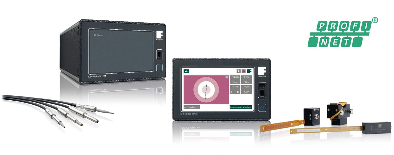
Fig.4: STATOGRAPH Product family
Due to the increasing digitalization in the future and the resulting intelligent monitoring of manufacturing processes, new requirements will also be placed on quality inspections. Thus, they should not only be used for sorting good and bad parts but also actively use the measurement results to detect and actively report back changes in the manufacturing process. Such as the wear of tools and the resulting deterioration of the surface. Such a change in the measured signals and approach to the sorting threshold can be detected with intelligent software solutions. This allows early intervention in the manufacturing process and the production of rejects can be avoided right from the start. These transform crack detection by means of eddy current from pure sorting to intelligent process monitoring, i.e. predictive maintenance.
The advantages of crack detection with eddy current at a glance:
- High testing speed and performance
- Good automation capability
- 100% inspection possible
- Objective result evaluation
- High reproducibility of the test
- Documentation and logging of test results
- No coupling media required
- Small defect resolutions possible
- Flexible application
- Intelligent filters and pattern recognition possible
- Possibility for process monitoring
Do you have any questions? Then feel free to contact our experts!
Share this
You May Also Like
These Related Stories

Crack testing: How does an eddy current test instrument work?

How can you check ball bearing rings for cracks and magnetic spots?
