For measuring electrical conductivity using eddy current, calibration standards are used to adjust and monitor the measuring instrument. These standards are essential for the measurement accuracy of the systems.
Currently, there are two types of conductivity standards. On the one hand, there are standards from the PTB (Physikalisch-Technische Bundesanstalt), which are determined with a direct current (DC) measurement. On the other hand, there are standards from the NPL (National Physical Laboratory) based on an alternating current (AC) measurement. Both methods and their advantages and disadvantages for measuring electrical conductivity using eddy current are described below.
1. Measurement of "DC" conductivity - calibration PTB
Conductivity is the reciprocal of the resistivity of a material. As a characteristic material parameter, the resistivity is determined from the voltage drop U that results when an impressed I current is applied to the defined cross-sectional areas A and length L of the material.
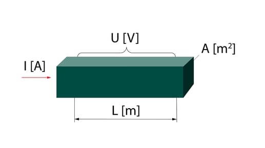
The conductivity measured in this way corresponds to the average conductivity value of the recorded material volume. Possible inhomogeneities of the material are averaged out over the entire volume.
1.1 Transfer of the "DC" conductivity values (PTB) to our "AC" conductivity meter
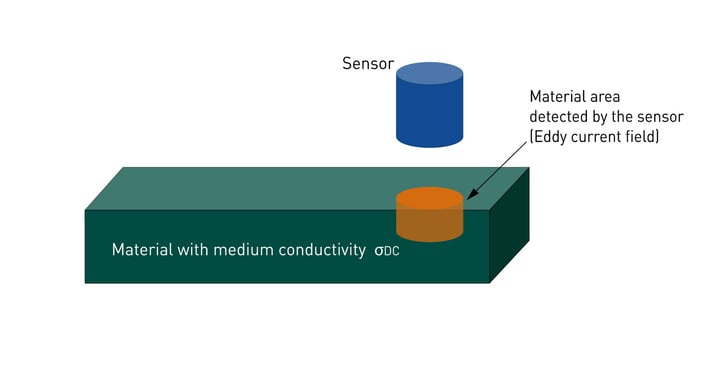
Compared to the DC measurement of the conductivity, only a small volume fraction of the material below the sensor is detected during the eddy current measurement. Under the active surface of the sensor (e.g. with Ø 14 mm) the eddy current density decreases exponentially with increasing depth, i.e. the recorded material volume is mainly concentrated in the surface area within this diameter.
 To directly transfer the average DC value of the material's conductivity to the eddy current measurement, the following requirements must be at least met:
- The material is completely homogeneous.
- The immediate surface area has the same conductivity as the entire material.
- The material is isotropic in terms of conductivity, i.e. there is no directional dependence.
These major prerequisites can hardly be fully implemented or controlled in practice. Process steps such as rolling, pressing, or surface treatment must always assume that these three influences are present. Depending on the material, these influences can differ significantly in their characteristics.
To determine possible errors when transferring the DC conductivity values to the AC measurement, the EU project G6RD-CT-2000-00210 was carried out between 2000 and 2003.
The following results and conclusions were drawn:
- Due to the possible material influences mentioned above, which cannot be fully recorded, an error of at least 0.5% of the measured value must be taken into account when switching from the DC values to the AC measurement. This error, caused by deviations between the DC and AC methods, represents a lower minimum limit for uncertainty, which cannot be fallen below.
- The DC / AC differences are material-specific. In particular, the manufacturing-related anisotropy influences and surface tensions result in conductivity deviations.
2. Measurement of the "AC" conductivity - calibration NPL
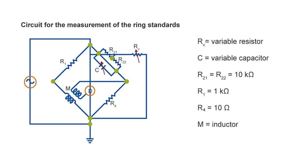
Another way of measuring electrical conductivity is by using a homogeneous alternating magnetic field, e.g., a toroidal coil. If the material is positioned in the coil, this changes its impedance. The electrical conductivity can be calculated based on this change, the electrical parameters, and the coil geometry. The primary standard consists of two halves. To measure the conductivity, this is brought together in the coil and the measurement is started.

2.1 Transfer of the "AC" conductivity values (NPL) to our "AC" conductivity meter
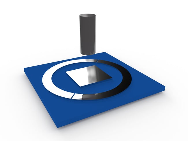
To transfer the now known electrical conductivity of the primary standard, a probe coil is used instead of the toroidal coil placed on the surface. The coil impedance is measured with the same electronics. The conductivity values of the primary standard are now correlated with the impedance of the probe coil.
Now, the conductivity value can be transferred to a secondary standard. The method for transferring the conductivity values from the primary standard (ring) to the secondary standard (plate) with a sensing coil is identical to the measuring principle of the mobile measuring device SIGMATEST from FOERSTER. Therefore, the uncertainty of the standards can be taken directly.
The electrical conductivity can be calculated with the following formula:
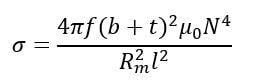
where:
- σ = the conductivity of the ring in S/m
- b = the mean width of the standard ring in m
- t = the mean thickness of the standard ring in m
-
μ₀ = the magnetic constant, 4𝝅x10-7H/m
- N = the number of turns in winding = 30
- R*m = the eddy current resistance
- l = the mean circumferences of the standard ring in m𝝅
3. Future of FOERSTER conductivity standards
With the new SIGMATEST 2.070, FOERSTER will return the conductivity standards to the AC measurement method of the NPL.
4. Testing based on PTB values still possible
Even after the changeover to the AC measurement method, you can set up the SIGMATEST 2.070 for DC standards. For this purpose, a calibration with two or more DC standards can be carried out. Accordingly, the conductivity curve stored in the instrument is adapted to the required range. In the future, FOERSTER recommends the use of standards, based on AC measurement.
Do you have any questions? Then feel free to contact our experts!

Share this

Crack testing: How do I set my filters and frequencies correctly?

Crack testing: How does an eddy current test instrument work?