1. Mobile UCI hardness testing
The portable hardness testing is usually carried out directly on-site on components with mobile devices, which also allows an initial evaluation of the results. The great advantage of portable measuring technology is:
- Easily movable for fast and selective decision making on site.
- Can be used where classic hardness testing (Vickers, Rockwell, Brinell) is not possible or impractical, such as in the area of incoming goods inspection, production control or maintenance on integrated components.
- In particular, systems with pin-shaped slim UCI probes can be used in all directions and applications are essentially limited only by accessibility to the measuring position.
With the invention of the UCI method (Ultrasonic Contact Impedance) in 1961, a hardness testing method was described for the first time that determines the Vickers hardness under load and thus records the full elastic and plastic material response (contact area). The system of Vickers diamond and vibrating rod, vibrating longitudinally in resonance, changes its vibration frequency upon material contact. The magnitude of the frequency increase always depends in the same way on the measuring force (1 N to 100 N) and on the mechanical parameters of the probe. The variable influencing factors only come from the test material, such as the coupling strength from the contact area and Young's modulus of the test material. The influence of the E-modulus, which is uniform for a material class, is compensated during the assembly of the probe by adjusting between 128 HV and 900 HV on 8 Vickers hardness reference blocks of forged tool steel (E-modulus approx. 205 to 210 GPa) calibrated by the MPA (Material Testing Authority Dortmund). These are hardened exclusively by thermal treatment and not by alloying additions. The resulting adjustment curve then sets the base for all calculations of Vickers hardness out of a frequency shift (comparative method). The inventor of the UCI method, Claus Kleesattel, had called this principle the "true SONODUR hardness", which can be determined exclusively from the frequency shift of a resonance vibration in the ultrasonic range.
Thus, according to the UCI standard DIN 50159-1, -2-2021 or ASTM A1038-2019, calibration is strictly speaking only successful if the nominal hardness value of the hardness reference block is reached without manual adjustment on the instrument by the operator. This is the case for UCI testing with hardness testers such as the SONODUR 3. Here, the calibration is usually retained even after a longer period of storage.
Calibration may fail if
- the hardness reference block is mounted on an unstable surface, such as a roller carriage, or if it rests on a dusty surface (so-called ringing - formation of disturbing component resonances).
- the shape and size of the hardness reference block is unfavorable for the UCI hardness testing (e.g. triangular blocks with 70 x 70 x 70 x 6 mm) and it has not been acoustically coupled.
- the operator does not guide the probe perpendicular to the component surface (max. ± 5 degrees to the perpendicular) or initiates transverse forces due to unfavorable handling. In this case, two or more operators should compare their results. Here, the elimination of obviously incorrect measurements is explicitly allowed if a corresponding measurement guideline from the Quality Management Manual is available.
- the probe is out of adjustment due to excessive mechanical stress. In this case, the probe should be returned to the manufacturer for inspection.
The absolute deviations from the block value are described in the DIN 50159-1 standard and in ASTM A1038 as a function of the measuring force and the hardness level (± 5 % for HV5UCI, mean value from 5 measurements).
1.1 Strengths of UCI hardness testing: an effective extension of Vickers testing
2. The UCI method: the physics
The UCI method - first used in 1965 under the name "SONODUR" - electronically evaluates and digitally displays the Vickers hardness indentation within fractions of a second. The resulting hardness value in units of Vickers is determined under load and a hardness value is calculated at a defined force (indentation force). This corresponds to the indentation surface after unloading.
2.1 Immediate acquisition of measured values
While the measuring probe is pressed onto the material, the vibrating rod of the probe performs longitudinal ultrasonic vibrations at approx. 78 kHz by means of piezoelectric excitation. The material coupling of the Vickers diamond creates a contact resistance, which initially causes a damping of the oscillation amplitude and simultaneously causes the oscillation frequency to increase in a characteristic manner. This damping is compensated for within a control loop. The frequency shift is determined exactly when a specified measuring force is reached, and in the case of hand-held probes, the Vickers hardness is calculated from this immediately. The hardness value is determined very quickly already in "forward motion", i.e. while the diamond is being pressed into the material - without waiting time or only after the probe has been lifted off the test material. This is the best way to minimize the influence of the measuring force on the operator. In the case of motorized probes, a programmable penetration time is waited for (1 to 99 s) due to the design. This allows the test to be simulated in the same way as the Vickers method and is used very successfully in the gravure printing industry on copper coatings with low measuring forces (1 N or 3 N). Here, a special spring system keeps the measuring force constant during the penetration process, which is currently not practicable with hand-held measuring probes.

Cylinder stacker in the gravure printing industry
2.2 Key variables influencing the frequency shift: the Young's modulus
The reference to the classical Vickers hardness testing is established, as explained, on MPA calibrated steel hardness reference blocks by recording the measured frequency shift for each hardness grade between approx. 120 and 900 HV (Fig. 1). The UCI probe acts like a high-frequency tuning fork whose inaudible frequency (elevation) depends on the degree of coupling of the Vickers diamond with the test material. Not only the contact area plays a role, but also the physical properties of the test part such as Young's modulus and Poisson's ratio. Hardness testers are calibrated to a specific Young's modulus in this case. The SONODUR 3, for example, for steel to Young's modulus of approx. 210 GPa. This corresponds to the majority of technical steel. Through this factory adjustment, the contribution of the acting force, the interaction of the resulting contact area between diamond and test piece, as well as the contribution of the elastic modulus from the resonating test material to the vibrating rod geometry or suspension are taken into account in the frequency shift.
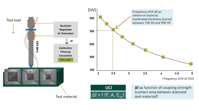
- Monitoring of Oscillation Frequency with material contact.
- Measurement of exact frequency at test load.
- Calculation of frequency shift Δf against the zero frequency f0 in air.
- Estimate of hardness value in HV from a reference curve (curve by FOERSTER).
Fig. 1: Principle of UCI testing with vibrating rod (left) in resonance and frequency shift depending on the coupling/hardness of the diamond with the test material (contact area).
2.3 The vibrating rod: the core of the probe assembly
2.4 The model of coupled mass-points
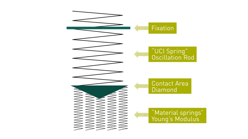
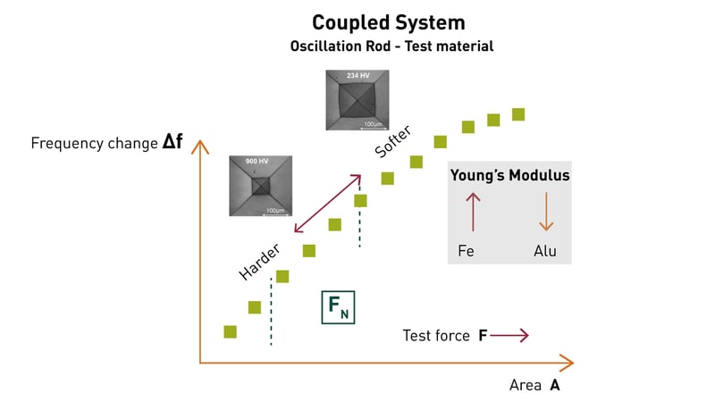
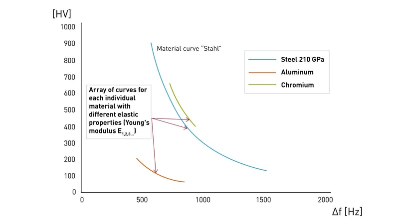
Fig. 1c: Different materials in terms of Young's modulus result in a set of curves
Please note that: different steel alloys do not differ in Young's modulus (Cr-Mn steels, etc.) and in this sense represent the "same material class". Austenitic stainless steels, duplex steels or Inconel may require individual adjustment by comparison with a suitable reference. Additionally, it should be noted that surface roughness may be included in the adjustment number. Therefore, it is important that the material processing should be as similar as possible.
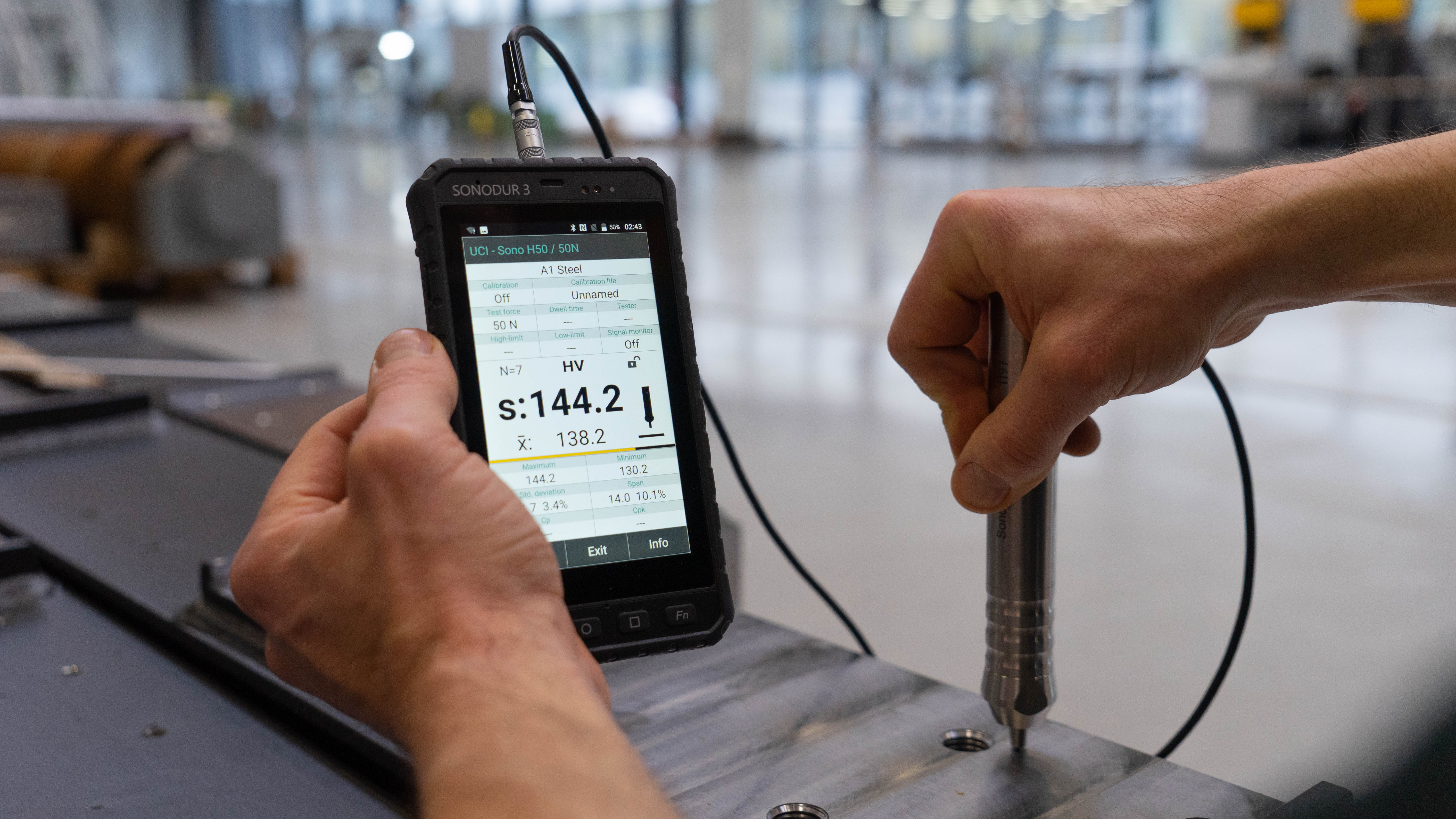
2.5 FOERSTER's answer to mobile UCI hardness testing: the SONODUR 3
|
The UCI measuring technology, as installed in the SONODUR 3, sets standards for the quality of the test results. The immediate acquisition of hardness values in "forward gear" enables measured values to be obtained quickly and operator errors can be largely eliminated. The reference to the classic Vickers hardness testing and thus to the standardized classic Vickers hardness scale lays the systemic foundation of the test procedure with SONODUR 3. The HV hardness scale makes it possible to measure all materials and test parts, from soft to hard. The method covers the entire hardness range. As a result, conversions to all common hardness scales are possible in real-time and at any time.
SONODUR 3 and UCI measuring probes Another big advantage of the SONODUR 3 measuring technology is the ability to make quick adjustments to materials that have different Young's modulus. The SONODUR 3 is therefore not only well equipped for your current applications but also optimally suited for future requirements. |

3. The concept of CAL adjustment number and conversion of hardness values
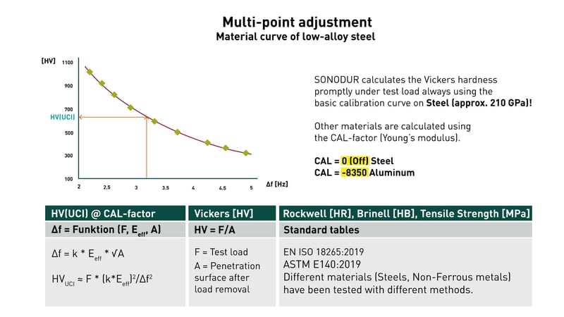
Fig. 2: Operations in determining the adjustment curve for low-alloy steel, which is created individually for each UCI probe.
The formula  shows the dependence of the frequency shift Δf on the rod property "k", the contact area A and the effective Young's modulus (from diamond and material).
According to the formula  , the calculated Vickers hardness HVUCI follows from the Vickers formula F/AHV with measuring force F and the indentation area AHV from the measured diagonals during optical testing (assumption AUCI=AHV). The course of the curve corresponds to a hyperbola.
If the agreement of the HVUCI value with the Vickers hardness HV = F/AHV is ensured (validation), the conversion to other hardness scales or to tensile strength can be performed for steel.
An instrument adjustment to materials with deviating Young's modulus (copper, aluminum, chrome, cast iron, etc.) is easily possible via a comparative measurement and only needs to be performed once, because the adjustment parameters (adjustment number, scale, material table, standard, measuring force as well as the name of the operator) can be saved in plain text and even sent by e-mail for other hardness testers. The company's own one-point adjustments "CAL" can now be used to create your own material tables for production control. The operator can immediately recognize the "correct" adjustment by the adjustment number displayed.
The adjustment number "CAL" is now used to adjust the material (Fig. 3), with the help of which the Vickers hardness is recalculated from the original adjustment curve (Fig. 2). The principle of comparison measurement and adjustment is common practice in non-destructive testing with e.g. eddy current (σ, µ, sensor data), ultrasound (c, probe data) or UCI (Young's modulus, vibrating rod). The numerical value is characteristic of the measuring process and can be programmed into the device at any time.
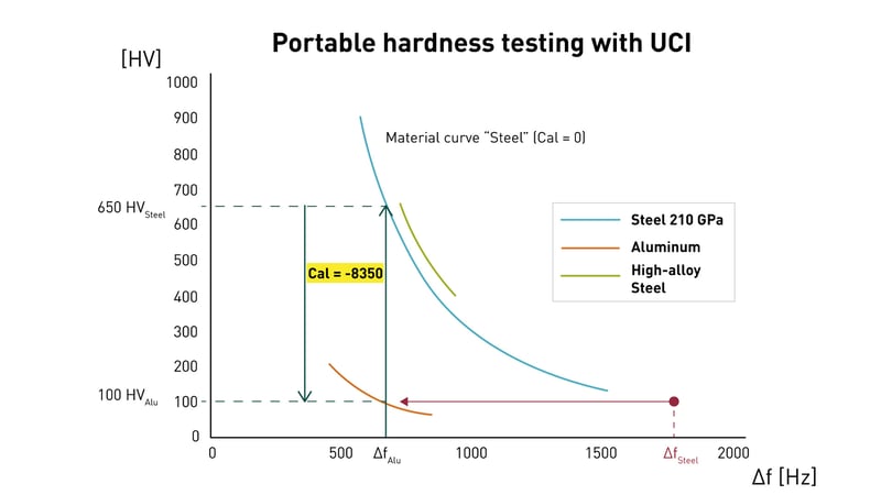
Fig. 3: Materials with deviating Young's modulus must be trained to the measuring device.
The coupling constant for aluminum with Young's modulus about 70 GPa causes a much smaller signal than for steel, which would lead to wrong results by comparison with the steel adjustment.
After determining the HV value, the Vickers measurement results can be displayed in other hardness units or tensile strengths using conversion functions from EN ISO 18265-2019 (formerly DIN 50150) or ASTM E140-18 (Fig. 2). The problem of applying revaluations within the classical hardness scales is discussed in detail in the standard texts. The surface or heat treatment condition and process control can affect the material response differently for the different hardness testing methods. SONODUR 3 includes all material tables in which Vickers hardness values are correlated with other scales.
In addition, the gauge automatically sets itself with the appropriate adjustment factor CAL if experience values are known (e.g. aluminum, table F4, F5 or T9 with CAL=-8350, Young's modulus approx. 70 GPa). From there, individual fine adjustments can be accomplished very quickly and easily by the comparative measurements mentioned above. Aluminum alloys with a high silicon content have an increased Young's modulus (approx. 104 GPa) and must therefore be measured using a Vickers reference with a modified CAL value for a viable measurement. In the case of aluminum, we recommend using the F5 (BS Standard, HB5/250) conversion table instead of F4 or T9 from ASTM E140, HB10/1000). In the case of copper, individual CAL numbers must be determined, as penetration depends on time and measuring force.
The concept of the CAL adjustment number has even more advantages, e.g. when the UCI measuring technology is used in automatic measuring equipment and possible (constant) influences due to the probe guidance and mounting have to be compensated.
The use of mobile hardness testing only makes sense if guidelines or specifications are available and the material properties and their history are known. It must also be ensured that comparability is possible when using testing methods with high forces (HRC, HB) and large penetration depths.
Which measuring device can best meet the requirements of mobile hardness testing?

With the SONODUR 3, FOERSTER offers a mobile high-tech all-rounder in the field of UCI hardness testing. The device works with cable-connected probes of the SONO-H/M/S series. These are available in different versions and test loads. Hand-held probes are available in the standard test loads 10 N, 30 N, 49 N and 98 N. Motor probes are available in 1 N, 3 N and 8.6 N versions. For tripod probes, there are test forces of 10 N, 49 N, 98 N.
Click here to learn more about mobile UCI hardness testing!

Share this
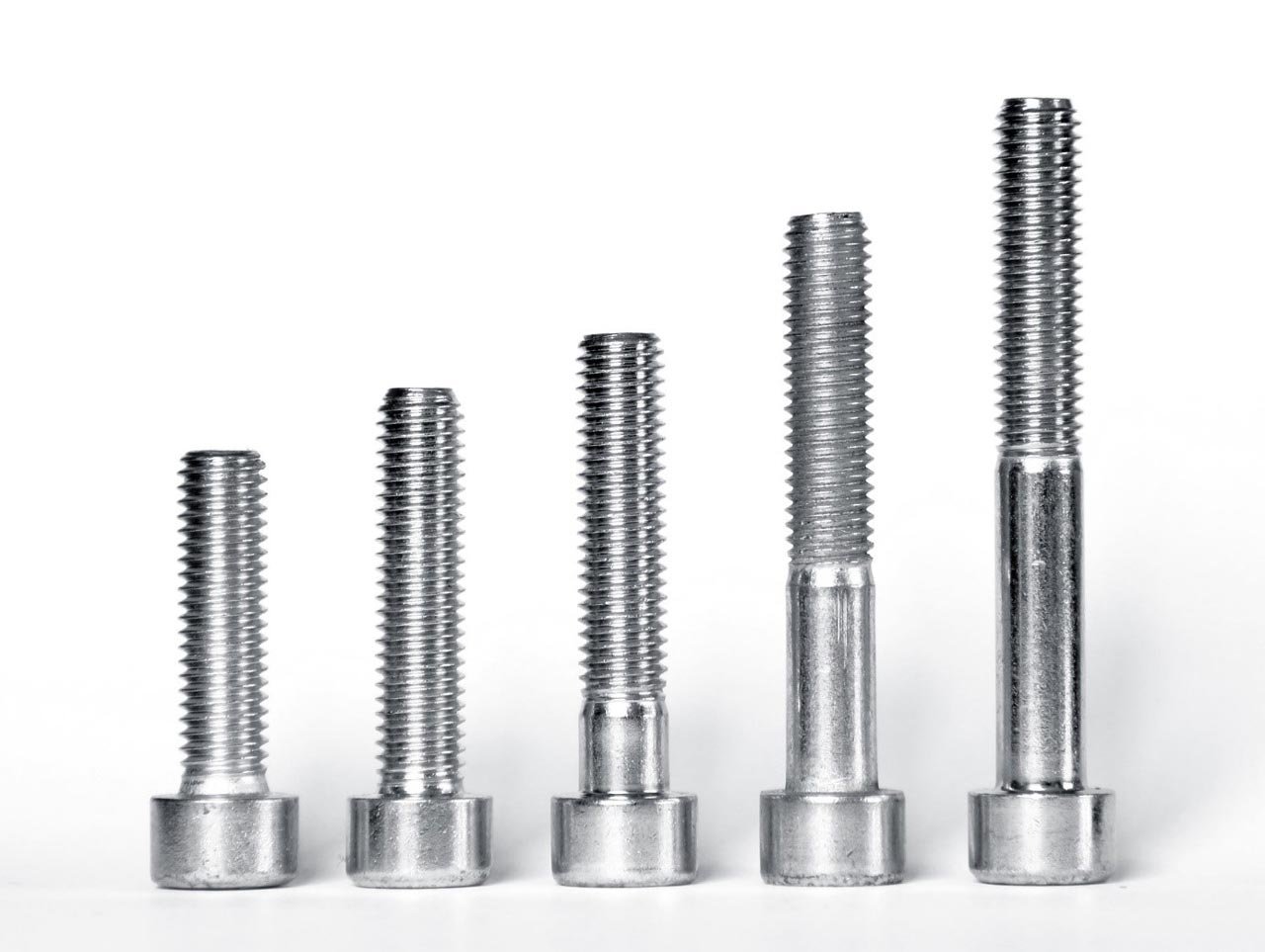
Hardness testing - so that fasteners & screws deliver what they promise
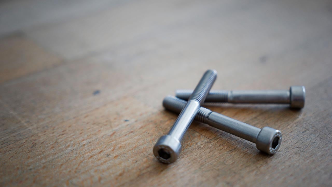
Fast UCI hardness measurement on screws and bolts: practical applications