Practical applications for fast UCI hardness measurement on screws and bolts
In the following article, after explaining some background to hardness measurement on small objects such as screws and bolts, we will discuss their practical implementation. This includes practical tips and experiences that facilitate measurements on these complex and quickly error-prone geometries.
Basic information on the use of UCI hardness measurement
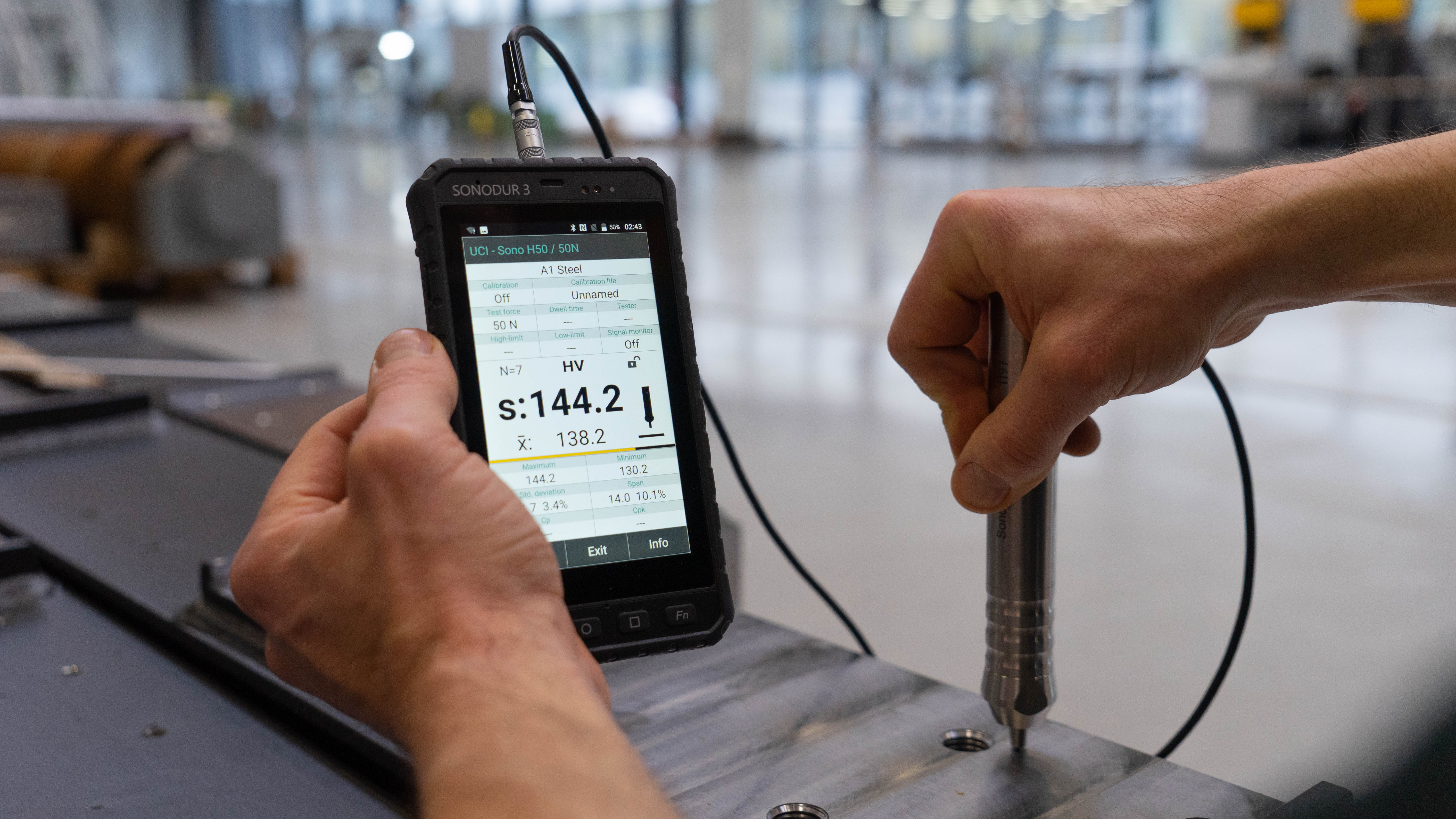
Mobile UCI (Ultrasonic Contact Impedance) hardness meters have established themselves in many areas of the metalworking industry as an important tool for quality assessment of processes. The mobile test systems works direction-independent and precisely with varying degrees of user-friendliness. The presentation of the results, their analysis and management is groundbreaking for the achievement of significant test results in portable hardness testing.
The solutions of test tasks are often not trivial. Caution is required so that disturbances from the material properties or the test lead can be excluded well enough from the results. Here, the user is required to inform himself about the possibilities and limits of the UCI procedure - as with all other test methods. Completely unprepared users risk failing quickly. In the end, after a short briefing and with a little manual skill, nothing stands in the way of a successful application of the hand-held UCI test probes.
What should be considered when measuring the hardness of screws and bolts?
In addition to good surface preparation, other boundary conditions must be observed. The UCI hardness test determines the Vickers hardness under load while the Vickers diamond is pressed into the material. The reference hardness scale is the Vickers system to which the UCI technology is always set. This may be necessary during operation if the modulus of elasticity of the test material differs significantly from standard steel (modulus of elasticity approx. 210 GPa).
The effect of the deviation can best be determined by a direct comparison with a classic hardness test system. Subsequently, for example when using the SONODUR 3 hardness tester, the deviation of the modulus of elasticity can easily be compensated via an adjustment (CAL number). The significance of these adaptations depends strongly on the possibilities of classical testing technology, especially when cylindrical surfaces have to be measured. The different penetration depths in the various hardness testing techniques must also be taken into account. For example, Rockwell C has a penetration depth of 100 μm at 50 HRC, which is a factor of 4 higher penetration depth compared to the Vickers method with 513 HV 10 and about 27 μm. Experience has shown that this can lead to significant differences in the hardness value on components with hardness gradients (surface hardening).
Thus,
- the nature of the material surface,
- the component geometry,
- the mechanical processing of the component,
- mechanical accessibility to the test position
- and its thermal history
have to be taken into account, as well as, in the case of small or thin parts,
- possible component resonances.
Depending on the task and test arrangement, it may be necessary to work with motor probes and very small test forces such as SONO 1M 1 N (HV 0.1) in order to avoid occurring component resonances at higher test forces.
Practical examples of measurements on screws and bolts
In the following, we present measurements carried out on different sections of the test components.
Measurements on the screw head
Basically, in the case of screw heads, the preferred measuring direction of the measuring probe is from top to bottom. To do this, the screw must be fixed with the screw head upwards via a vice or screwed into a suitable bracket. Especially with small parts, component vibrations (disturbing resonances) are to be expected at the outer edge of the head, which can be minimized by appropriate measures (acoustic coupling, screwing in or embedding). Resonances occur locally at non-predetermined locations. However, they can usually be detected very well due to their strong scattering and extreme values that are far outside the expected range.
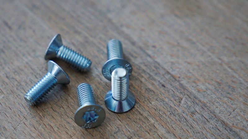 Image description: Small countersunk head screws for measurement on the screw head after heat treatment. The thread is not accessible for UCI measurement in this case . The measurement on the shaft was not in demand, as Vickers tests are not practicable in that position.
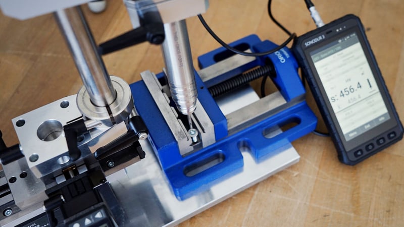 Image description: Measuring arrangement for testing the screw head with head clamped in the vice with SONO H10L, long version probe. The essential criterion is the distribution of the measurements on the head at a close distance and observation of the repeatability R. A value below 5.0% can be considered a very good value. Five measurements are often sufficient for a significant result.
Before starting the measurement, the linearity of the test probe is usually checked (calibrated) with five measurements on a hardness reference plates. This is done to check whether the probe works accurately and unexpected results can only have something to do with the test situation.
| Mean of 5 measurements | 284,5 | HV 1 UCI | 615,7 | HV 1 UCI |
| Hardness plate | 289 | HV 1 | 602,0 | HV 1 |
| Deviation | -4,5 | HP | 13,7 | HP |
| Deviation in % | -1,6 | % | 2,3 | % |
| Limited deviation according to standard Din 50159-1 |
±5 |
% |
±6 |
% |
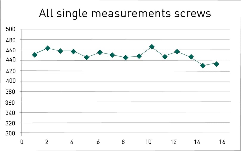
The measurement results on all screw heads summarized in a row show a uniform result for all three screws. Five measuring points each stand for a screw with the mean values for screw 1, 2 and 3 of 455 HV 1 UCI, 452 HV 1 UCI and 444 HV 1 UCI. All measurement results were taken into account for logging.
Measurements on the shaft
Preferred measuring direction is again from top to bottom, whereby the orientation of the screw should be in the direction of the operator's gaze, with good illumination of the measuring position. Here it is important that when measuring by hand, the probe tip is placed in the direction of view on the apex of the circumference. This makes it easier to carry out the measurement right there. If the positioning is off, small transverse forces are introduced into the resonance rod of the test probe by the eccentric attachment, which lead to an additional frequency shift and thus to the calculation of a lower hardness value. In practice, this means that, unlike the screw head, the measurement arrangement is more difficult and you have to expect measured value scattering under the actual value. And this is all the more the thinner the diameter becomes.
Measuring a screw on the shaft
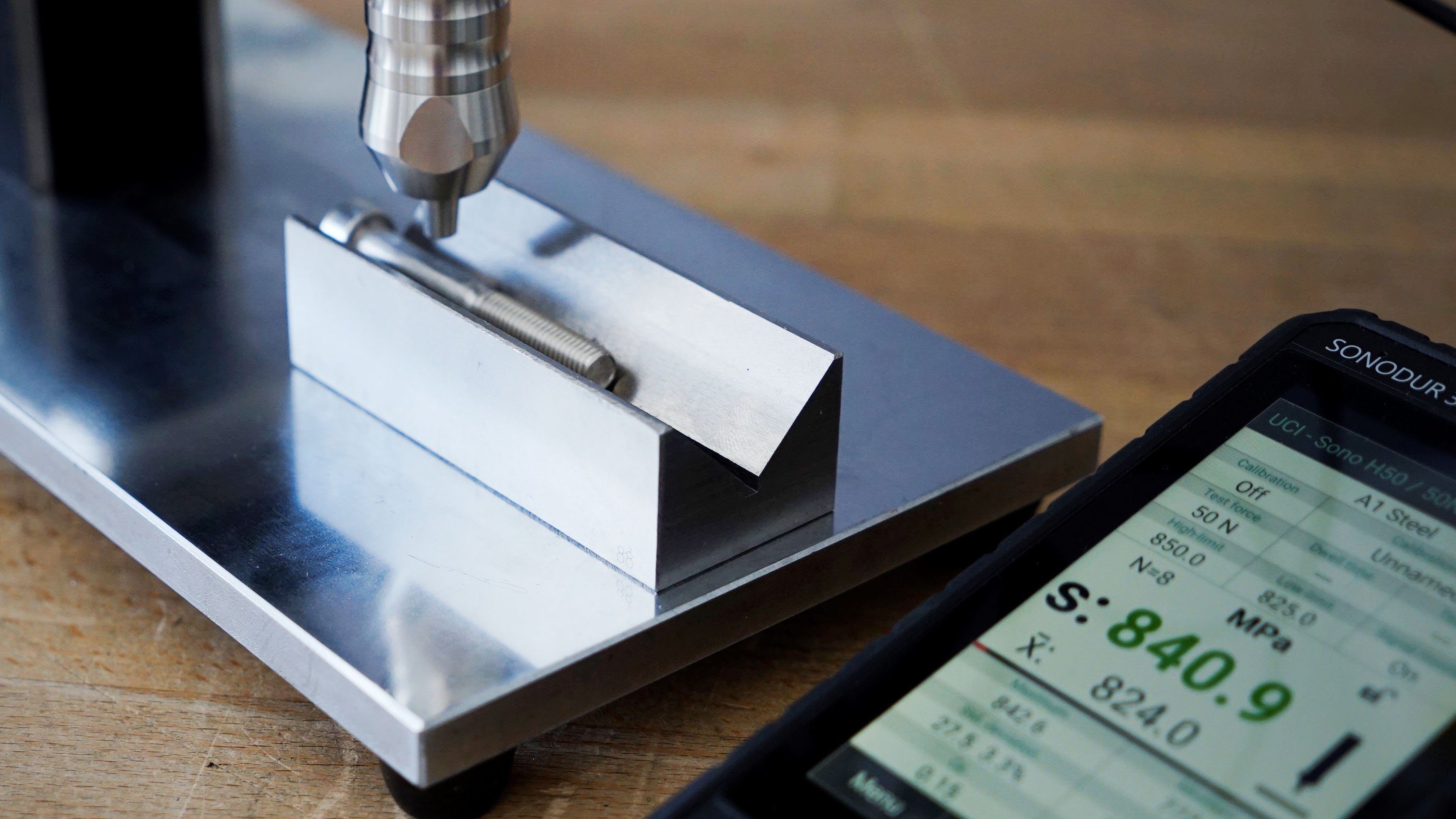
Here, the observation of repeatability plays an important role, as does the assignment of the minimum and maximum values relative to the mean value. If a clear asymmetry is observed in the result display of the device at a distance from the mean value, this is an unmistakable sign of an incorrect measurement. Of course, this applies in general, but especially for minimum measured values with curved surfaces, as an "overshooting" is quite unlikely, unless you have to expect the occurrence of isolated component resonances.

Image description: Image from the SONODUR 3 with the results tableau
Obvious incorrect measurements can easily be excluded from the observation by touching the maximum or minimum value in the result table of the device. This is automatically opened and displayed in order to then be excluded from further consideration.
In the case of screw and bolt testing, outliers shall in any case be declared as such for significant results. Values excluded from consideration are part of the original test report for additional control purposes. If corrections have been initiated in the results table, a further series of measurements is recommended to verify the measures, as far as possible. The final results (averages) should differ only slightly from each other.
Measurements in the thread base
The screw must be large enough for the diamond to be attached within the thread. It should be noted here that the diamond does not touch the wall and the measurements are made exactly in the thread bottom, otherwise transverse forces can occur again. These measurement tasks are not very common due to their complexity and limited applicability.
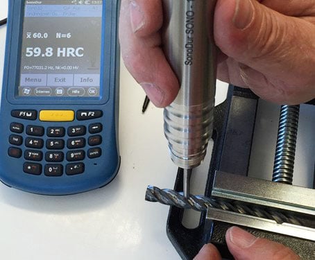
Image description: Example of the measurement in the clamping groove on a drill tip. Here SONO H10L, long version.
Measurements on mild steel screws
As a test setup, comparative measurements were carried out on several experimental structural steel screws (burnished or Zinn-coated), with Rockwell C as a reference scale. The customer had set an HRC measuring point in each case. It must be taken into account that a tolerance of ±1 HRC is permitted on hardness reference plates. Three calibration measurements are actually to be carried out (EN ISO 6706). The measurements were taken with HV 10 UCI (SONO H100 handheld measuring probe) on the head and shaft. The screws were held in a vice or placed on a prism base (measurements on the shaft).
The best conditions would be present if the screws were tightened into a fastening. The UCI measurements were distributed near the Rockwell test impressions. No UCI readings were excluded. In the case of the coated screws, the Rockwell impressions were placed in the ground surfaces. The burnished surfaces were not machined.
The UCI results have confirmed the HRC measurements, whereby the measurements on the coated screws are generally slightly increased and the measured values are greater than with the burnished screws. Reasons could be sought in the thermal processing by the coating process.
Results with probe SONO H100 in HRC UCI
| Burnished screws | 1 | 2 | 3 | 4 |
| 36 HRC | 37,0 | 38,4 | ||
| 37 HRC | 37,2 | 38,4 | 38,5 | |
| 38 HRC | 38,9 | 399,4 | 38,5 | |
| Härtebereich: 37-39 HRC | ||||
| Coated screws | 1 | 2 | 3 | 4 |
| 36 HRC | 40,7 | 41,5 | ||
| 37 HRC | 40,0 | |||
| 38 HRC | 42,1 | 42,2 | 41,6 | |
| Härtebereich: 37-39 HRC |
Based on the criteria for safety screws, the burnished screws are more likely to be assigned to class 10.9 with the tolerance range 32 – 39 HRC according to the data sheet. In contrast, the coated screws are in class 12.9 with 39 – 44 HRC.
Example of a measurement protocol
| File | \My Documents\Basic\Screw-38-Head-2_01 |
| Date | 15. June 2022 |
| Start of Meas. | 10:43 |
| Probe/Test Force | Sono100/100N |
| Dwell Time | 0 sec |
| Orientation | 0° |
| Material | Steel |
| Nrom; HV->HRC | THIS IS 18265 |
| Adj. Number | 0 |
| Limits | Off |
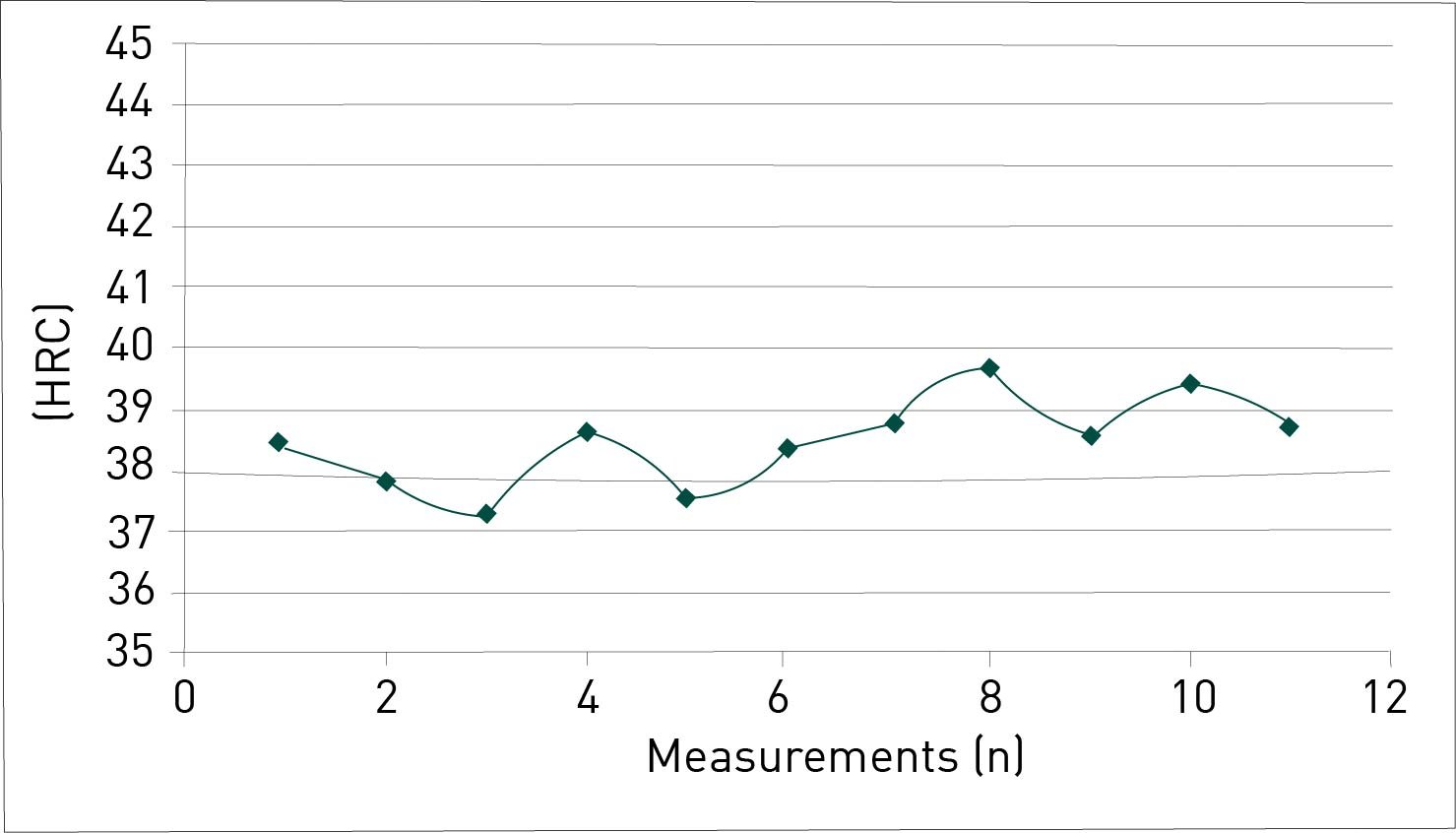
| Number | 11 |
| Mean | 38,5 HRC |
| Std. Deviation | 0,7 HRC; 1,9% |
| Maximum | 39,7 HRC |
| Minimum | 37,3 HRC |
| R | 24,6 HRC; 6,3% |
| Remarks | Second side measured at the head, since the support of the head was uneven on the side of the HRC impression. The screw was not fixed, but only applied. |
| 1 | 38,4 | HRC | 376 | HP |
| 2 | 37,8 | HRC | 371 | HP |
| 3 | 37,3 | HRC | 366 | HP |
| 4 | 38,6 | HRC | 378 | HP |
| 5 | 37,5 | HRC | 368 | HP |
| 6 | 38,3 | HRC | 376 | HP |
| 7 | 38,7 | HRC | 379 | HP |
| 8 | 39,7 | HRC | 389 | HP |
| 9 | 38,5 | HRC | 377 | HP |
| 10 | 39,4 | HRC | 386 | HP |
| 11 | 38,7 | HRC | 379 | HP |
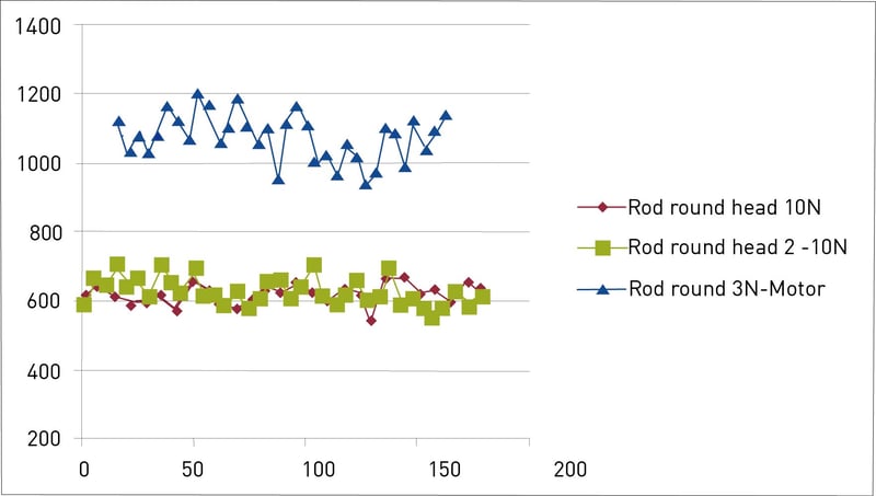
Measurements with motor probes on a steel bolt
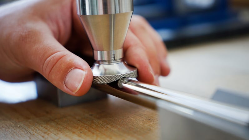
If there is sufficient space for aids such as prism probe feet, measurement with a motor measuring probe and prism probe base is recommended on cylindrical surfaces or thin coatings. The diameter can be adjusted with a knurled screw. Due to the self-centering via the prism, reliable results can be achieved even with very small test forces, as here with the 3N motor measuring probe SONO M3.
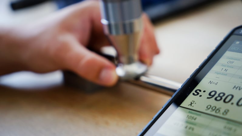
This example is a steel bolt with a diameter of 6 mm. The surface of the austenitic steel (here 1.4571) is colsterized (carburization by diffusion at a low temperature of about 300 °C). The surface hardness was measured with approx. 1100 HV 0.3 UCI, whereby one can assume a hardening depth of approx. 20 μm (hardening depth at 550 HV). Tests with slightly higher test force have yielded approx. 600 HV UCI (manual test probe SONO H10, HV 1 UCI), due to the very thin hardening layer. The surface hardness on the head was identical to the results on the shaft.
The results in comparison:
| Measurements | ARE H10 | ARE H10 | ARE M3 | HEAD ARE M3 |
| Number of measurements | 27 | 37 | 34 | 10 |
| Average | 634 HV | 622 HV | 1078 HV | 1042 HV |
| Sigma | 26 HV; 4.4% | 27 HV; 4.6% | 68 HV; 6.3% | 38 HV; 3.7% |
| Maximum | 670 HV | 705 HV | 1200 HV | 1115 HV |
| Minimum | 541 HV | 555 HV | 940 HV | 994 HV |
| R | 129 HV; 17.6% | 150 HV; 15.4% | 261 HV; 24.2% | 122 HV; 11.7% |
Summary: Multiple solutions for mobile hardness measurement on screws and bolts with the SONODUR 3
SONODUR 3 offers multiple solutions for a wide variety of applications for process control in production and maintenance. With the currently widest product range from microhardness (1 N, HV 0.1 UCI) to macro hardness (100 N, HV 10 UCI), a wide variety of geometries, component sizes and textures can be reliably measured. Compared to classical methods, the measurements can be carried out very quickly, in hard-to-reach and complicated places in any direction. Due to the large number of measurements, suspicious measurement results can also quickly be evaluated in the device and ultimately significant results can be achieved.
Using the example of screws and bolts, comparative measurements have been successfully carried out using classic hardness testing methods, which suggests the use of SONODUR 3 in production. As with other measurement and test methods, boundary conditions must be taken into account in the testing and evaluation of results in order to minimize negative influences. In combination with classic hardness testing and the wide selection of probe geometries, SONODUR 3 is like a "test laboratory on site".

Share this
How UCI Technology and SONODUR 3 Boost Precision and Efficiency

Effective mobile hardness testing for airline quality assurance